Treat Flux like your intern. Tell it what you'd like to build and it'll get to work. You can also ask it questions, brainstorm ideas, and teach it your preferences. Learn More
The component Q1 is a transistor with the manufacturer's part number MMBT4403. Transistors, like the one in this schematic, are versatile devices used for signal amplification, switching, voltage regulation, signal modulation, and many other functions.
This transistor is in a PNP configuration. PNP transistors work in a way that when there's no voltage difference between the base (B) and emitter (E), the transistor is "on" and current can flow from the collector (C) to the emitter (E), effectively working as a current source. When the voltage at the base (B) is pulled low, the current flow from the collector (C) to the emitter (E) is "off", or stopped.
Now, for the exact role of Q1 in this circuit, we need more information about how the pins are connected. However, given what we have, the PNP transistor might be used here for a variety of functions, such as acting as a switch, an amplifier, or part of a power regulation stage. Some more typical roles for a PNP transistor like this could include:
Switch: If the transistor is controlling power to a part of the circuit. In this case, changing the base-emitter voltage would effectively switch power on or off to that part of the circuit.
Amplifier: If this circuit is dealing with analog signals, it could be part of an amplifier stage—perhaps for the load cell signal.
Power regulation: If this circuit needs a stable voltage source, the transistor could be part of a regulator stage.
Without more specifics about the connections and overall goal of your circuit, it's hard to say the exact role of the transistor. Nonetheless, its general function would be along the lines of controlling current flow based on the input at the base pin (B).
2y
Someone is typing...
2
SCK
A+
VDD
A-
A-
VCC
VCC
DAT
VCC
SCK
A+
DAT
VDD
VCC
VDD
VCC
VCC
R1
Resistance
20kΩ
R3
Resistance
100 Ω
R2
Resistance
8.2kΩ
R5
Resistance
10kΩ
R4
Resistance
100 Ω
C7
Capacitance
10uF
J1
C6
Capacitance
10uF
J4
Q1
C4
Capacitance
0.1uF
C2
Capacitance
0.1uF
J2
JP1
C5
Capacitance
0.1uF
C3
Capacitance
0.1uF
U1
L1
Inductance
3.3uH
C1
Capacitance
0.1uF
No files yet
Reviews
Documents
Documents are markdown text files which describe project goals, capture details, or even simulation outputs.
Assets
nv_logo.svg
nv_logoDefault
thumb.PNG
thumbThumbnail
SparkFun Load Cell Amplifier - HX711
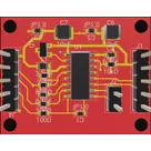
The SparkFun Load Cell Amplifier is a small breakout board for the HX711 IC that allows you to easily read load cells to measure weight. By connecting the amplifier to your microcontroller you will be able to read the changes in the resistance of the load cell, and with some calibration you’ll be able to get very accurate weight measurements. This can be handy for creating your own industrial scale, process control or simple presence detection.
Properties
Properties describe core aspects of the project.
Pricing & Availability
Distributor
Qty 1
Digi-Key
$0.02–$1.00
LCSC
$0.55–$0.81
Mouser
$0.03–$0.23
Controls
Welcome 👋
Flux helps you build PCBs faster with an AI teammate!
Create your account to collaborate, stay updated, fork your own version, and get instant answers from our AI agent.
aitor51
copilot