Pin Function Grouping
Thought
93 days
- Set D's Pin Orientation to "Left"
- Set D's Section to "Communication"
- Set D's Pin Group to "MCU Logic Interface"
- Set D's Pin Type to "Input"
- Set D's Pin Description to "CAN transmit data input"
- Set GND's Pin Orientation to "Bottom"
- Set GND's Section to "Ground"
- Set GND's Pin Group to "Ground"
- Set GND's Pin Type to "Ground"
- Set GND's Pin Description to "Ground connection"
- Set GND's Terminal Type to "ground"
- Set VCC's Pin Orientation to "Top"
- Set VCC's Section to "Power"
- Set VCC's Pin Group to "Power / 3V3"
- Set VCC's Pin Type to "Power In"
- Set VCC's Pin Description to "3.3V supply input"
- Set R's Pin Orientation to "Right"
- Set R's Section to "Communication"
- Set R's Pin Group to "MCU Logic Interface"
- Set R's Pin Type to "Output"
- Set R's Pin Description to "CAN receive data output"
- Set Vref's Pin Orientation to "Right"
- Set Vref's Section to "Analog"
- Set Vref's Pin Group to "Reference Output"
- Set Vref's Pin Type to "Output"
- Set Vref's Pin Description to "VCC divided reference output"
- Set CANL's Pin Orientation to "Left"
- Set CANL's Section to "Communication"
- Set CANL's Pin Group to "CAN Bus Differential Pair"
- Set CANL's Pin Type to "Bi-Directional"
- Set CANL's Pin Description to "CAN low bus line"
- Set CANH's Pin Orientation to "Left"
- Set CANH's Section to "Communication"
- Set CANH's Pin Group to "CAN Bus Differential Pair"
- Set CANH's Pin Type to "Bi-Directional"
- Set CANH's Pin Description to "CAN high bus line"
- Set Rs's Pin Orientation to "Left"
- Set Rs's Section to "Control"
- Set Rs's Pin Group to "Mode / Slope Control"
- Set Rs's Pin Type to "Input"
- Set Rs's Pin Description to "Mode and slope control"
R
CANH
GND
Rs
CANL
D
Vref
Reviews
 A generic fixed inductor suitable for rapid circuit topology development. The footprint automatically adapts based on the selected package, supporting standard SMD sizes (e.g., 0402, 0603, 0805) as well as well-known inductor packages such as SDR1806, PA4320, SRN6028, and SRR1260. Standard inductor values: 1.0 nH, 10 nH, 100 nH, 1.0 µH, 10 µH, 100 µH, 1.0 mH 1.2 nH, 12 nH, 120 nH, 1.2 µH, 12 µH, 120 µH, 1.2 mH 1.5 nH, 15 nH, 150 nH, 1.5 µH, 15 µH, 150 µH, 1.5 mH 1.8 nH, 18 nH, 180 nH, 1.8 µH, 18 µH, 180 µH, 1.8 mH 2.2 nH, 22 nH, 220 nH, 2.2 µH, 22 µH, 220 µH, 2.2 mH 2.7 nH, 27 nH, 270 nH, 2.7 µH, 27 µH, 270 µH, 2.7 mH 3.3 nH, 33 nH, 330 nH, 3.3 µH, 33 µH, 330 µH, 3.3 mH 3.9 nH, 39 nH, 390 nH, 3.9 µH, 39 µH, 390 µH, 3.9 mH 4.7 nH, 47 nH, 470 nH, 4.7 µH, 47 µH, 470 µH, 4.7 mH 5.6 nH, 56 nH, 560 nH, 5.6 µH, 56 µH, 560 µH, 5.6 mH 6.8 nH, 68 nH, 680 nH, 6.8 µH, 68 µH, 680 µH, 6.8 mH 8.2 nH, 82 nH, 820 nH, 8.2 µH, 82 µH, 820 µH, 8.2 mH #generics #CommonPartsLibraryjharwinbarrozo16.6k
- A generic fixed capacitor ideal for rapid circuit topology development. You can choose between polarized and non-polarized types, its symbol and the footprint will automatically adapt based on your selection. Supported options include standard SMD sizes for ceramic capacitors (e.g., 0402, 0603, 0805), SMD sizes for aluminum electrolytic capacitors, and through-hole footprints for polarized capacitors. Save precious design time by seamlessly add more information to this part (value, footprint, etc.) as it becomes available. Standard capacitor values: 1.0pF, 10pF, 100pF, 1000pF, 0.01uF, 0.1uF, 1.0uF, 10uF, 100uF, 1000uF, 10000uF 1.1pF, 11pF, 110pF, 1100pF 1.2pF, 12pF, 120pF, 1200pF 1.3pF, 13pF, 130pF, 1300pF 1.5pF, 15pF, 150pF, 1500pF, 0.015uF, 0.15uF, 1.5uF, 15uF, 150uF, 1500uF 1.6pF, 16pF, 160pF, 1600pF 1.8pF, 18pF, 180pF, 1800pF 2.0pF, 20pF, 200pF, 2000pF 2.2pF, 22pF, 220pF, 2200pF, 0.022uF, 0.22uF, 2.2uF, 22uF, 220uF, 2200uF 2.4pF, 24pF, 240pF, 2400pF 2.7pF, 27pF, 270pF, 2700pF 3.0pF, 30pF, 300pF, 3000pF 3.3pF, 33pF, 330pF, 3300pF, 0.033uF, 0.33uF, 3.3uF, 33uF, 330uF, 3300uF 3.6pF, 36pF, 360pF, 3600pF 3.9pF, 39pF, 390pF, 3900pF 4.3pF, 43pF, 430pF, 4300pF 4.7pF, 47pF, 470pF, 4700pF, 0.047uF, 0.47uF, 4.7uF, 47uF, 470uF, 4700uF 5.1pF, 51pF, 510pF, 5100pF 5.6pF, 56pF, 560pF, 5600pF 6.2pF, 62pF, 620pF, 6200pF 6.8pF, 68pF, 680pF, 6800pF, 0.068uF, 0.68uF, 6.8uF, 68uF, 680uF, 6800uF 7.5pF, 75pF, 750pF, 7500pF 8.2pF, 82pF, 820pF, 8200pF 9.1pF, 91pF, 910pF, 9100pF #generics #CommonPartsLibraryjharwinbarrozo1.5M
- A generic fixed resistor ideal for rapid circuit topology development. Its footprint automatically adapts based on the selected package case code—supporting 0402, 0603, 0805, 1203, and many other standard SMD packages, as well as axial horizontal and vertical configurations. Save precious design time by seamlessly add more information to this part (value, footprint, etc.) as it becomes available. Standard resistor values: 1.0 ohm, 10 ohm, 100 ohm, 1.0k ohm, 10k ohm, 100k ohm, 1.0M ohm 1.1 ohm, 11 ohm, 110 ohm, 1.1k ohm, 11k ohm, 110k ohm, 1.1M ohm 1.2 ohm, 12 ohm, 120 ohm, 1.2k ohm, 12k ohm, 120k ohm, 1.2M ohm 1.3 ohm, 13 ohm, 130 ohm, 1.3k ohm, 13k ohm, 130k ohm, 1.3M ohm 1.5 ohm, 15 ohm, 150 ohm, 1.5k ohm, 15k ohm, 150k ohm, 1.5M ohm 1.6 ohm, 16 ohm, 160 ohm, 1.6k ohm, 16k ohm, 160k ohm, 1.6M ohm 1.8 ohm, 18 ohm, 180 ohm, 1.8K ohm, 18k ohm, 180k ohm, 1.8M ohm 2.0 ohm, 20 ohm, 200 ohm, 2.0k ohm, 20k ohm, 200k ohm, 2.0M ohm 2.2 ohm, 22 ohm, 220 ohm, 2.2k ohm, 22k ohm, 220k ohm, 2.2M ohm 2.4 ohm, 24 ohm, 240 ohm, 2.4k ohm, 24k ohm, 240k ohm, 2.4M ohm 2.7 ohm, 27 ohm, 270 ohm, 2.7k ohm, 27k ohm, 270k ohm, 2.7M ohm 3.0 ohm, 30 ohm, 300 ohm, 3.0K ohm, 30K ohm, 300K ohm, 3.0M ohm 3.3 ohm, 33 ohm, 330 ohm, 3.3k ohm, 33k ohm, 330k ohm, 3.3M ohm 3.6 ohm, 36 ohm, 360 ohm, 3.6k ohm, 36k ohm, 360k ohm, 3.6M ohm 3.9 ohm, 39 ohm, 390 ohm, 3.9k ohm, 39k ohm, 390k ohm, 3.9M ohm 4.3 ohm, 43 ohm, 430 ohm, 4.3k ohm, 43K ohm, 430K ohm, 4.3M ohm 4.7 ohm, 47 ohm, 470 ohm, 4.7k ohm, 47k ohm, 470k ohm, 4.7M ohm 5.1 ohm, 51 ohm, 510 ohm, 5.1k ohm, 51k ohm, 510k ohm, 5.1M ohm 5.6 ohm, 56 ohm, 560 ohm, 5.6k ohm, 56k ohm, 560k ohm, 5.6M ohm 6.2 ohm, 62 ohm, 620 ohm, 6.2k ohm, 62K ohm, 620K ohm, 6.2M ohm 6.8 ohm, 68 ohm, 680 ohm, 6.8k ohm, 68k ohm, 680k ohm, 6.8M ohm 7.5 ohm, 75 ohm, 750 ohm, 7.5k ohm, 75k ohm, 750k ohm, 7.5M ohm 8.2 ohm, 82 ohm, 820 ohm, 8.2k ohm, 82k ohm, 820k ohm, 8.2M ohm 9.1 ohm, 91 ohm, 910 ohm, 9.1k ohm, 91k ohm, 910k ohm, 9.1M ohm #generics #CommonPartsLibraryjharwinbarrozo1.5M
- An electrical connector acting as reusable interface to a conductor and creating a point where external circuits can be connected.Terminal
- General Purpose Thick Film Standard Power and High-Power Chip Resistor 47 kOhms ±5% 0.125W, 1/8W Chip Resistor 0805 (2012 Metric) Automotive AEC-Q200 Thick Film Features: - RMCF – standard power ratings - RMCP – high power ratings - Nickel barrier terminations standard - Power derating from 100% at 70ºC to zero at +155ºC - RoHS compliant, REACH compliant, and halogen free - AEC-Q200 compliantjharwinbarrozo1.2M
- 10 µF 16 V Aluminum - Polymer Capacitors Radial, Can - SMD 30mOhm 2000 Hrs @ 105°C #commonpartslibrary #capacitor #aluminumpolymer #radialcanjharwinbarrozo1.2M
- Battery Holder (Open) Coin, 20.0mm 1 Cell SMD (SMT) Tab bate or batt #forLedBlinkjharwinbarrozo700.5k
- A momentary or non-latching switch which causes a temporary change in the state of an electrical circuit only while the switch is physically actuated. SWITCH TACTILE SPST-NO 0.05A 24Vjharwinbarrozo490.7k
- Straight 3 pin 5mm 3-pin Pitch 5mm 15A 1.5 300V Screw terminal block 01x03 #screwblock #connector #commonPartsLibraryjharwinbarrozo537.9k


SN65HVD230DR
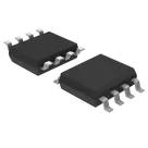
1/1 Transceiver Half CANbus 8-SOIC
The SN65HVD230DR is a high-speed Controller Area Network (CAN) transceiver designed to interface a CAN protocol controller with the physical two-wire CAN bus. It operates as a differential line driver and receiver, translating logic-level signals into robust bus-level signals suitable for automotive, industrial, and distributed control applications. The device is optimized for reliable communication in electrically noisy environments and supports low-power operation, making it suitable for systems requiring energy efficiency and extended operational stability.
This transceiver conforms to widely adopted CAN physical layer standards and is intended for use in systems requiring high data integrity, fault tolerance, and electromagnetic compatibility. It integrates protection features and supports standby functionality to reduce system power consumption when communication is inactive.
Functional Overview
The device provides bidirectional signal conversion between a CAN controller and the differential CAN bus lines. It features a transmit data input and a receive data output, enabling full-duplex communication at the protocol level. The driver stage generates differential output signals on the bus, while the receiver stage detects and translates bus signals back into logic-level data.
An internal control mechanism allows the device to enter a low-power standby mode, reducing current consumption when active communication is not required. The transceiver includes slope control capability to manage signal edge rates, which helps minimize electromagnetic interference and improves signal integrity across the network.
Electrical Characteristics
The transceiver operates from a single low-voltage supply and is designed for compatibility with modern microcontrollers and digital logic systems. It provides differential output drive capability with controlled rise and fall characteristics. The receiver is designed with high input sensitivity and noise immunity to ensure accurate signal detection under varying bus conditions.
The device includes thermal protection and safeguards against bus faults, including short-circuit conditions. Its internal circuitry is designed to maintain stable operation across a wide range of environmental conditions and supply variations.
Interface Requirements
The logic interface is compatible with standard digital input and output levels, allowing direct connection to a CAN controller. The bus interface consists of two differential lines that connect to the CAN network. Proper termination and layout practices are required to ensure optimal communication performance and compliance with CAN network design guidelines.
Operating Conditions
The device is intended for operation across a broad temperature range suitable for industrial and automotive environments. It maintains functional integrity under typical voltage fluctuations and environmental stresses encountered in embedded systems.
Protection and Reliability Features
The transceiver incorporates protection mechanisms to guard against overcurrent, thermal overload, and electrostatic discharge. It is designed to maintain communication reliability even in the presence of transient disturbances and electrical noise.
Packaging and Integration
The SN65HVD230DR is provided in a compact surface-mount package suitable for automated assembly. Its pin configuration supports straightforward integration into printed circuit board designs with minimal external components.
Properties
Integrated Circuit
Texas Instruments
SN65HVD230DR
U
parametric-v1
Pricing & Availability
DPN | Stock | Qty 1 |
|---|---|---|
5 | 0–223K | $0.9822–$2.343 |
4 | 0 | $0.00 |
1 | 4.6K | $0.56812 |
2 | 4.8K–61K | $0.4152–$0.6891 |
1 | 61K | $2.84 |
1 | 3.5K | $0.00 |
15 | 0 | $0.00 |
Controls
Welcome 👋
Flux accelerates your PCB design with AI.
Create your account to start using this component and bring your ideas to life.