Chat

Welcome to Flux

Treat Flux like your intern. Tell it what you'd like to build and it'll get to work. You can also ask it questions, brainstorm ideas, and teach it your preferences. Learn More

Explain this part
Write a part description
Describe each pin
Operating conditions
Electrical max ratings
Part Specifications
Application circuits
Verify Part Details
Recommend similar parts
Check availability & lifecycle
create a high level mermaid block diagram of this project. Include key component...

@copilot create a high level mermaid block diagram of this project. Include key component's manufacturer part number in each block whenever possible.
2y
Given the information provided in your project description, let's create a high-level Mermaid block diagram to depict the SIM800L module and its connections. The SIM800L is a Quad-band Network Mini GPRS GSM Breakout Module manufactured by Simcom. Although the individual manufacturer part numbers for the components like RST (reset), NET (network), VCC, etc. are not specified in your details, the main component is the SIM800L module itself. We'll create the diagram focusing on the primary connections and functionalities offered by this module.

Diagram


SIM800L $SIM800L Module<br>Manufacturer: Simcom$ VCC: Power Supply GND: Ground RST: Reset NET: Network Indicator TXD: Transmit Data RXD: Receive or Data DTR: Data Terminal Ready RING: Ring Indicator $MIC+: Microphone Positive, MIC-: Microphone Negative$ $SPK+: Speaker Positive, SPK-: Speaker Negative$
  • VCC and GND represent the power connections. The SIM800L operates with a supply voltage typically around 3.4V to 4.4V. Please ensure you provide a smooth power supply within this range to avoid any damage.
  • RST (Reset) is used to reset the module.
  • NET (Network Indicator) displays the network status and can flash at different rates to indicate various states like searching for a network or connected to a network.
  • TXD and RXD are for serial communication, allowing the module to interface with microcontrollers or computers.
  • DTR (Data Terminal Ready) is used to control the sleep mode of the module.
  • RING indicates incoming calls.
  • MIC+ & MIC- are the pins for connecting a microphone to the module. This allows audio input for calls or recording.
  • SPK+ & SPK- are the pins for connecting a speaker, thus enabling audio output for calls or alerts.
This diagram presents an overview of key connections for the SIM800L module, primarily focusing on its functionalities and how it interfaces with other components or systems. Do keep in mind, actual implementation details such as part numbers for the microphone, speaker, and additional components like regulators or specific connectors are assumed to be standardized but are not detailed in your project information.
2y
Someone is typing...
2

No files yet

Documents

    Documents are markdown text files which describe project goals, capture details, or even simulation outputs.

    Assets

    step

    SIM800L v10.step

    3D_SIM800L v103D Model
    image-removebg-preview.png

    image-removebg-preview.png

    image-removebg-previewThumbnail
    kicad_mod

    SIM800L v10_4.kicad_mod

    FP_SIM800L v10_4Footprint

    SIM800L Module

    SIM800L Module thumbnail
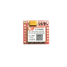
    SIM800L Quad-band Network Mini GPRS GSM Breakout Module. #componentpartslibrary #gprs #gsm

    Properties

    Module

    Simcom

    SIM800L

    U

    Pricing & Availability

    Distributor

    Qty 1

    Controls