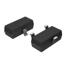
Treat Flux like your intern. Tell it what you'd like to build and it'll get to work. You can also ask it questions, brainstorm ideas, and teach it your preferences. Learn More
Certainly! Here's a step-by-step plan to verify the functionality of your circuit using the S8050 NPN BJT transistor:
Table
Step
Task
Instructions
1
Component Identification
Ensure that you have all the required components: S8050 transistor, and possibly resistors, capacitors, etc.
2
Initial Setup
Open your project in Flux. Place the transistor on the canvas. Ensure Q1 is the identifier for the S8050.
3
Pin Identification
Identify the transistor pins: B (Base), C (Collector), E (Emitter).
4
Base Connection
Connect B to a suitable bias resistor (say $R_1$) to control the transistor. Connect $R_1$:2 to B:1
5
Collector Setup
Connect C to the load (e.g., $R_2$). Connect $R_2$:1 to C:1
6
Emitter Connection
Connect E to the ground node. Connect E:1 directly to ground.
7
Power Supply
Apply a suitable DC voltage to the circuit: Vcc to one end of $R_2$. Vcc to $R_2$:2
8
Simulation Configuration
Configure a basic DC analysis or transient analysis in Flux to verify that the circuit works as expected.
9
Run Simulation
Run the simulation and observe the current flow. Verify that the transistor is operating in the desired region.
10
Check Voltage Levels
Use measurement tools to check the voltages at Base, Collector, and Emitter to ensure proper biasing.
11
Iterate and Modify
If necessary, iterate and modify resistor values to achieve desired current and voltage levels.
12
Document and Conclude
Once functionality is verified, document the results and any changes made for future reference.
Detailed Connections
Base Biasing:
Connect $R_1$:2 to B:1. The other end of $R_1$, $R_1$:1, will be connected to a voltage source (bias supply).
Load:
Connect $R_2$:1 to C:1.
Connect $R_2$:2 to the Vcc (positive voltage supply).
Emitter to Ground:
Connect E:1 to GND.
Assumptions
Biasing Resistor $R_1$: Let's assume a typical value of 10kΩ.
Load Resistor $R_2$: Let's assume a typical value of 1kΩ.
Supply Voltage (Vcc): Let's assume 5V for initial testing.
Feel free to adjust the values based on your specific requirements and feedback from the simulation results. If you have any specific assumptions or component values, do let me know!
2y
Someone is typing...
2
E
C
B
No files yet
Reviews
Documents
Documents are markdown text files which describe project goals, capture details, or even simulation outputs.
mstronics
copilot
Table
- Base Biasing:
- Connect $R_1$:2 to B:1. The other end of $R_1$, $R_1$:1, will be connected to a voltage source (bias supply).
- Load:
- Connect $R_2$:1 to C:1.
- Connect $R_2$:2 to the Vcc (positive voltage supply).
- Emitter to Ground:
- Connect E:1 to GND.
Assumptions