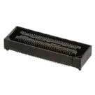
Part Review and Datasheet Verification
Thought for 5 mins 5 sec
Here’s the full review and cross-check for QSH-030-01-L-D-A.
- Available part information (from the part project)
- MPN: QSH-030-01-L-D-A
- Manufacturer: Samtec
- Part type: Connectors
- Mount: Surface Mount
- Designator prefix: J
- Description: “Samtec QSH Series 0.5mm Pitch 60 Way 2 Row Straight PCB Socket, Surface Mount, Solder Termination”
- Datasheet: https://suddendocs.samtec.com/catalog_english/qsh.pdf
- Datasheet URL presence and update
- A datasheet URL is already set on this part. No update required.
- Datasheet metadata extraction (QSH series; specific to -030, -01, -L, -D, -A where available)
Part number decoding
- Series: QSH
- Positions per row: 30 (code “030”) → total contacts: 60 (2 rows)
- Lead style: 01
- Plating: L = 10 µin (0.25 µm) Gold on contact, Matte Tin on tail
- Type: D = Single-ended (not differential-pair)
- Option: A = Pick & place pad (polyimide film)
- Pitch: 0.50 mm (0.0197 in)
- Rows: 2 (A/B)
Electrical and environmental
- Current rating: 2 A per contact (with 2 pins powered)
- Ground plane current (if applicable in options using ground plane): 25 A per ground plane (1 ground plane powered)
- Voltage rating: 175 VAC / 247 VDC
- Operating temperature range: -55 °C to +125 °C
Mechanical and stack height
- General series dimensions include typical widths/heights such as (3.05) 0.120, (3.25) 0.128, (7.24) 0.285, (7.49) 0.295, etc. (see drawing)
- Mated stack height with QTH (by QTH lead style):
- 01: A height 4.27 mm; with QSH 5.00 mm
- 02: 7.26 mm; with QSH 8.00 mm
- 03: 10.27 mm; with QSH 11.00 mm
- 04: 15.25 mm; with QSH 16.00 mm
- 05: 18.26 mm; with QSH 19.00 mm
- 07: 24.24 mm; with QSH 25.00 mm
- 09: 13.26 mm; with QSH 14.00 mm
- Note: Processing conditions can affect mated height.
Recommended PCB land pattern (QSH-XXX-01-X-D-XXX)
- The datasheet provides a full recommended layout for QSH-XXX-01-X-D-XXX including typical values such as:
- 0.5001 mm pitch (0.01969 in)
- Repeating dimensions like 0.279 mm, 0.815 mm, 6.20 mm, 14.504 mm, 4.890 mm, etc.
- Symmetry about the centerline and connector envelope keep-out notes
- For -SD/-DS (screw-down) options, a different application drawing is referenced
- Soldering guidance (per Samtec SMT process guidance): connectors typically must withstand up to 230 °C for 30–60 s, and may see up to 260 °C for 10 s (refer to Samtec processing docs)
Pin arrangement and numbering
- QSH has two rows (A and B) at 0.50 mm pitch. QSH-030-D = 30 contacts per row → total 60 contacts.
- The catalog page is largely graphical; explicit text for “Pin 1 locator” could not be extracted from the text layer. Conventionally, rows are labeled A/B, with numbering sequence shown in the figure on the page.
Mating connectors
- Board mate: QTH (QTH/QSH system)
- Cable mates: HQCD, HQDP
- Cross-check: schematic symbol and footprint vs datasheet
Findings
-
Total contacts mismatch (critical):
- Datasheet for QSH-030-D: 2 rows, 30 contacts per row → total contacts: 60.
- Schematic symbol contains 64 terminals (components labeled as “Terminal” with designators 1..64; no nets yet).
- Footprint contains 64 pads (Pads 1..64 in the PCB node tree).
- Impact: This is a high-risk mismatch. If left uncorrected, it can cause net mapping errors, assembly issues, and functional failures. The part is advertised as “60 Way 2 Row,” so symbol and footprint should present exactly 60 signal pads (30 per row), with any additional mechanical features (e.g., pick & place pad, mechanical holes) implemented as non-electrical features, not numbered contacts.
-
Row labeling and numbering:
- Datasheet: two rows (A/B) at 0.50 mm pitch; numbering figure is present.
- Current symbol: appears to use generic untyped “Terminal” objects numbered sequentially; there’s no explicit A/B row labeling or a clear pin 1 indication in the symbol.
- Risk: Ambiguity during schematic capture and layout correlation. Suggest adopting A/B row labels and confirming the correct numbering sequence/pin 1 location per the datasheet figure.
-
Pitch and land pattern:
- Datasheet: pitch is 0.50 mm and provides detailed recommended PCB layout for QSH-XXX-01-X-D-XXX.
- Current footprint: Pad count visible; specific pad sizes/spacing not displayed in the node index. Unable to verify actual pad pitch/geometry from available layout nodes alone.
- Action needed: Confirm pad pitch (should be 0.50 mm) and land pattern dimensions match the recommended PCB layout for QSH-XXX-01-X-D-XXX.
-
Option -A (Pick & place pad):
- Datasheet: “A” = pick & place pad (polyimide film).
- Footprint: From the node listing alone, additional non-electrical features (pick & place pad zone) aren’t visible. If modeled, it should not be implemented as numbered signal pads. Ensure the pick & place pad is handled as a mechanical/assembly feature, not as an electrical pad.
-
Soldering and mechanical holes:
- The catalog page references PTH features for certain variants/processes (paste-in-hole notes are present in the recommended layout text). For the -01 lead style single-ended variant (no screw-down), ensure any PTH or mechanical holes in the footprint exactly match the recommended layout for this specific option and are not misrepresented as electrical pads.
Summary of required corrections
- Reduce the symbol to exactly 60 signal pins (30 per row) and align numbering with the datasheet’s A/B row scheme and pin 1 orientation.
- Reduce the footprint to exactly 60 electrical pads for signals; represent any mechanical features (pick & place pad, optional holes) as non-electrical/mechanical where appropriate.
- Verify pad pitch is exactly 0.50 mm and all pad and spacing dimensions match the “RECOMMENDED PCB LAYOUT FOR QSH-XXX-01-X-D-XXX.”
- Add a clear pin 1 locator on the symbol and footprint silkscreen/assembly layers per the datasheet figure.
If you want, I can update the symbol and footprint to the correct 60-pin configuration and align the land pattern to the datasheet-recommended layout.
Run full DRC/ERC
Check footprint pitch
Verify Samtec pin-1
Confirm MPN in BOM