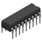
Part Data Review and Validation
Thought for 1 min 17 sec
I found no Datasheet URL set on the part. Princeton’s current site did not expose a live PT2272 PDF, so I’m using a distributor-hosted copy of the Princeton datasheet as the best available official source.
Worked for 3 mins 50 sec
Completed the PT2272M4 review and added the best available Princeton datasheet URL:
https://www.mouser.com/datasheet/2/737/PT2272-2489449.pdf.The symbol pin numbers/names match the datasheet, and the DIP-18 footprint matches the PT2272-M4 DIP package option. Main issues flagged: package property is incorrectly set to
TO, pin descriptions are missing, and pin electrical types are all unspecified; details are in the project document pt2272m4-part-review.
Fix the package property, pin descriptions, and electrical pin types from the datasheet.
Thought for 9 sec
I’ll update the part/package metadata and annotate each terminal with datasheet-based pin descriptions and electrical pin types, then re-read the schematic to verify.
Thought for 1 min 31 sec
Updated and verified the PT2272M4 part metadata:
Package or Case Code is now 18-DIP.All 18 pins now have datasheet-based
Pin Description values and valid electrical Pin Type settings: A0–A7/DIN = Input, D0–D3/VT = Output, OSC1/OSC2 = Passive, VSS = Ground, VCC = Power In. No open items remain.Run part checks
Update review doc
Verify footprint pads
Check publishing readiness
Name
Pin #
Type
Part Type
Pin Description
Pin Orientation
A0
1
Input
Terminal
Tri-state address input A0; must match corresponding PT2262 encoder address state.
Left
A1
2
Input
Terminal
Tri-state address input A1; must match corresponding PT2262 encoder address state.
Left
A2
3
Input
Terminal
Tri-state address input A2; must match corresponding PT2262 encoder address state.
Left
A3
4
Input
Terminal
Tri-state address input A3; must match corresponding PT2262 encoder address state.
Left
A4
5
Input
Terminal
Tri-state address input A4; must match corresponding PT2262 encoder address state.
Left
A5
6
Input
Terminal
Tri-state address input A5; must match corresponding PT2262 encoder address state.
Left
A6
7
Input
Terminal
Tri-state address input A6; must match corresponding PT2262 encoder address state.
Left
A7
8
Input
Terminal
Tri-state address input A7; must match corresponding PT2262 encoder address state.
Left
VSS
9
Ground
Terminal
Negative supply / ground pin.
D3
10
Output
Terminal
Momentary data output D3 for the PT2272-M4 four-data-output variant.
Right
D2
11
Output
Terminal
Momentary data output D2 for the PT2272-M4 four-data-output variant.
Right
D1
12
Output
Terminal
Momentary data output D1 for the PT2272-M4 four-data-output variant.
Right
D0
13
Output
Terminal
Momentary data output D0 for the PT2272-M4 four-data-output variant.
Right
DIN
14
Input
Terminal
Encoded serial data input from the RF/IR receiver front end.
Right
OSC2
15
Passive
Terminal
Oscillator pin OSC2; connect external timing resistor between OSC1 and OSC2.
Right
OSC1
16
Passive
Terminal
Oscillator pin OSC1; connect external timing resistor between OSC1 and OSC2.
Right
VT
17
Output
Terminal
Valid transmission output; asserts when a valid encoded transmission is decoded.
Right
VCC
18
Power In
Terminal
Positive supply input; datasheet operating range VCC = 4 V to 15 V.
PT2272M4