Part Verification and Datasheet Update
Thought for 1 min 49 sec
I reviewed the part metadata, current part project, and the official datasheet workflow. For part-project verification, the key checks are: confirm an existing
What I found
Part metadata
Datasheet URL, use the datasheet as the source of truth for package/pin metadata, and compare every terminal and footprint pad against the datasheet pin list .The project already has a
Datasheet URL set, so I did not need to search the web or update that property. The existing project properties show:- MPN: MP2731GQC-0000-Z
- Manufacturer: Monolithic Power Systems (MPS)
- Package: QFN
- Designator Prefix: IC
From the official datasheet, the device is:
- MP2731GQC-0000-Z
- Monolithic Power Systems, Inc.
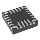
- QFN-26 (3.5 mm x 3.5 mm) / mechanical package name 26L FCQFN (3.5 x 3.5 mm)
- 26 pins
- Description: 4.5 A, I2C-controlled switch-mode battery charger with NVDC power path and USB OTG
- Input operating range: 3.7 V to 16 V
- Sustainable voltage: 22 V
- Charge current: up to 4.5 A
- Switching frequency: 1.35 MHz
- OTG output: 4.8 V to 5.5 V
- OTG current: up to 3.0 A
- Junction temperature: -40°C to +125°C
- Package: QFN-26, 3.5 mm x 3.5 mm
The overall identity looks correct:
- MPN matches the datasheet.
- Manufacturer matches the datasheet.
- The project is clearly intended to represent the MP2731 charger PMIC.
- Many terminal names align with valid datasheet pins, such as IN, PMID, SW, BST, STAT, INT, NTC, VNTC, AGND, SYS, BATT, SDA, DISC, OTG, and ILIM.
There are major symbol/footprint consistency problems relative to the datasheet:
1. Pin count mismatch
- Datasheet: 26 pins
- Current schematic symbol: 30 terminal components
- Current footprint: 30 pads visible in the layout data
This is the biggest issue. The part project should match the datasheet pin count exactly, including any exposed pad only if the datasheet explicitly lists it as a pin . The extracted datasheet content did not identify an exposed pad pin for this package, so the current 30-pin symbol/30-pad footprint appears incorrect.
2. Extra pins that should not exist
The datasheet pin table ends at pin 26 , but the current symbol includes:
These are not present in the extracted datasheet pin list and should be flagged as likely erroneous.
3. Missing / misassigned repeated pins
The datasheet lists repeated functions at these exact pin numbers:
DPon pins 1 and 26PGNDon pins 5, 6, 7VREFon pins 13, 14SCLon pins 19, 20
In the current project:
- Pin 14 is PGND_4, but the datasheet says pin 14 should be a second VREF.
- Pins 28 and 29 are extra
PGNDentries not supported by the datasheet. - Pin 30 is an extra
SCLentry not supported by the datasheet. - The symbol uses split naming such as DP_1, DP_2, SCL_1, SCL_2, which is acceptable stylistically, but the pin numbers must still match the datasheet exactly.
The current terminals have
5. Pin types are all Pin Number and Pin Type, but I did not see meaningful Pin Description properties populated on the symbol terminals. The verification workflow expects short pin descriptions to be set from the datasheet for IC-style parts . So this is an incompleteness issue, even where pin names are otherwise correct.Unspecified
Every terminal I inspected had
Pin Type: Unspecified, including STAT, BST, IN, SYS, and others. For a part project, pin types should be assigned from the datasheet mapping rules, such as:IN-> Power InPGND,AGND-> GroundSTAT,INT-> OutputCE,OTG,DISC,ILIM,NTC-> InputSDA-> Bi-DirectionalSCL-> InputSYS, possiblyVREFdepending on intended modeling -> likely Power Out / Output context-dependent Using exact datasheet-derived pin typing is recommended for ERC quality .
The layout contains one footprint with 30 pads, mirroring the 30 terminals in the symbol. Since the official package is QFN-26 / 26L FCQFN, this strongly suggests the footprint is also mismatched to the datasheet package definition. In other words:
- Symbol pin count is wrong
- Footprint pad count is wrong
- Symbol and footprint are internally consistent with each other, but both are inconsistent with the official datasheet
- Datasheet URL: already present, no update needed
- MPN/manufacturer: correct
- Description/package family: broadly correct
- Symbol: mismatch
- Footprint: mismatch
- Pin descriptions: missing/incomplete
- Pin types: missing/incomplete
Table
| Area | Expected from datasheet | Current project | Result |
|---|---|---|---|
| Pin count | 26 | 30 | Mismatch |
| Package name | QFN-26 / 26L FCQFN 3.5 x 3.5 mm | QFN only | Incomplete |
| Pin 14 | VREF | PGND_4 | Mismatch |
| Pins 27-30 | Do not exist | Present | Mismatch |
| Pin descriptions | Short datasheet-derived descriptions | Not populated | Missing |
| Pin types | Datasheet-mapped | All Unspecified | Missing |
If you want, I can do the next step and repair the part project by:
- correcting the terminal set to match the 26-pin datasheet,
- fixing wrong pin names/numbers,
- assigning proper pin types and short pin descriptions,
- and tightening the package metadata to QFN-26 / 26L FCQFN (3.5 x 3.5 mm).
Fix the part project
Add pin descriptions
Check footprint details
Save review notes