Chat

Welcome to Flux

Treat Flux like your intern. Tell it what you'd like to build and it'll get to work. You can also ask it questions, brainstorm ideas, and teach it your preferences. Learn More

Explain this part
Write a part description
Describe each pin
Operating conditions
Electrical max ratings
Part Specifications
Application circuits
Verify Part Details
Recommend similar parts
Check availability & lifecycle
please give me a schematic to build a power supply for 12 v

@copilot please give me a schematic to build a power supply for 12 v
2y
Sure, I can guide you through building a basic power supply circuit using the LM317T to output a stable 12V. The LM317T is a highly versatile regulator that allows for an output voltage to be precisely adjusted to your desired value using just two resistors.
Given that your project incorporates an LM317T and we're aiming for a 12V output, here's a basic schematic setup:
Components Needed:
  • LM317T Voltage Regulator (U1)
  • Input capacitor (Cin): 0.1uF (C1)
  • Output capacitor (Cout): 1uF (C2)
  • Adjust capacitor (Cadj): 10uF (Optional, improves ripple rejection) (C3)
  • Resistor for setting output voltage (R1): 240 Ohm
  • Resistor for setting output voltage (R2): Adjust as per formula to get 12V output
Connections:
  1. Input Capacitor (Cin) Connection:
    • Connect C1:1 to U1:VI (Pin 3)
    • C1:2 to Ground
  2. Adjust Capacitor (Cadj) Connection (Optional):
    • Connect C3:1 to U1:ADJ (Pin 1)
    • C3:2 to Ground
  3. Output Capacitor (Cout) Connection:
    • Connect C2:1 to U1:VO (Pin 2)
    • C2:2 to Ground
  4. Adjusting Resistor (R1) Connection:
    • Connect one end of R1 to U1:VO (Pin 2)
    • Connect the other end of R1 to U1:ADJ (Pin 1)
  5. Output Resistor (R2) Connection:
    • Connect one end of R2 to U1:ADJ (Pin 1)
    • Connect the other end of R2 to Ground
Voltage Calculation:
To set the LM317 for a 12V output, you'll use the formula for the output voltage of an LM317:
Vout=1.25V×(1+R2R1)+IADJR2V_{\text{out}} = 1.25V \times \left(1 + \frac{R2}{R1}\right) + I_{\text{ADJ}}R2
Assume:
  • Vref=1.25VV_{\text{ref}} = 1.25V
  • IADJ0I_{\text{ADJ}} \approx 0 for simplicity, as its contribution is minimal
For a 12V output and given that R1=240ΩR1 = 240\Omega, we rearrange the formula to solve for R2R2:
12V=1.25V×(1+R2240Ω)12V = 1.25V \times \left(1 + \frac{R2}{240\Omega}\right)
R2=(12V/1.25V)1240ΩR2 = \frac{(12V / 1.25V) - 1}{240\Omega}
Calculating R2 gives us a value of about ( 1.82k\Omega ). A standard value of ( 1.8k\Omega ) for R2 will closely achieve the 12V desired output.
Remember, the input voltage (VI) should be at least 2-3V higher than the desired output voltage due to the dropout voltage of the LM317T, making a minimum input voltage of around 15V advisable for a 12V output.
Please adjust the capacitor values as needed based on your specific applications, especially regarding the input ripple and load requirements. Capacitors with higher values can be used to improve the smoothness of the output voltage if your circuit is sensitive to voltage fluctuations.
2y
Someone is typing...
2

No files yet

Documents

    Documents are markdown text files which describe project goals, capture details, or even simulation outputs.

    Assets

    step

    TO-220-3_Vertical.step

    3D3D Model
    kicad_mod

    TO-220-3_Vertical.kicad_mod

    FOOTPRINT_V5Footprint
    LM317T.png

    LM317T.png

    LM317TThumbnail
    LM317_3PinPackage

    LM317_3PinPackage

    defaultDefault

    LM317T

    LM317T thumbnail
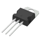
    Linear Voltage Regulator IC Positive Adjustable 1 Output 1.5A TO-220-3 #commonpartslibrary #integratedcircuit #powermanagement #voltageregulator

    Pricing & Availability

    Distributor

    Qty 1

    Controls