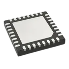
Part Review and Datasheet Verification
Worked for 2 mins 23 sec
Completed the L9961TR part review and saved the detailed findings in
l9961tr-part-review.Key flags: the Datasheet URL was already set to ST’s official PDF, but the project properties show incorrect
Part Type: Inductors and Package or Case Code: TO; official package is VFQFPN 5x5x1 32L P0.5. The main pinout mismatches are pin 13 and pin 27, which the ST-sourced pin table lists as GND while the symbol currently uses TM_ENTER and TM1.Suggested next steps:
- Correct the package and part-type properties.
- Verify pins 13/27 directly in the PDF before editing the symbol.
- Populate Pin Type and Pin Description properties from the datasheet.
- Verify exact QFN exposed-pad and perimeter-pad geometry before fabrication.

Populate Pin Type and Pin Description properties from the datasheet.
Thought for 5 sec
I’ll update each terminal’s Pin Type and Pin Description from the ST L9961 datasheet pin table, then re-read the schematic to verify the properties landed correctly.
Thought for 1 min
The first pass added the datasheet detail, but Flux warned that several Pin Type values were non-standard; I’m normalizing them to Flux’s supported Pin Type options while keeping the detailed electrical behavior in Pin Description.
Thought for 53 sec
Populated Pin Type and Pin Description for all 33 terminals and verified the updates in the schematic.
I normalized Pin Type values to Flux-supported options while preserving datasheet-specific details like analog input, open-drain, active level, and pull-down behavior in Pin Description. Pins 13 and 27 are now treated as GND terminals based on the ST pin table.
Fix properties and review
Fix part properties
Verify symbol pinout
Check footprint geometry
Run ERC DRC
Refine this doc
Ask about this doc
L9961TR Part Review
Date: 2026-06-16
Reviewed project part metadata
- Project/part: L9961TR
- Manufacturer Part Number: L9961TR
- Manufacturer: STMicroelectronics
- Description: STMicroelectronics chip for consumer battery management applications up to 5 cells
- Published part UID: 378a4c67-6a43-4c57-88e1-181569521462
- Current Datasheet URL: https://www.st.com/resource/en/datasheet/l9961.pdf
- Existing project properties found:
- Part Type: Inductors
- Manufacturer Name: STMicroelectronics
- Package or Case Code: TO
- Manufacturer Part Number: L9961TR
- Designator Prefix: IC
- Datasheet URL: https://www.st.com/resource/en/datasheet/l9961.pdf
Official datasheet / web reference
The Datasheet URL was already set, so no Datasheet property update was required. Web lookup confirmed the official ST datasheet and ST product/eStore pages:
- Official ST datasheet: https://www.st.com/resource/en/datasheet/l9961.pdf
- ST alternate datasheet resource: https://www.st.com/content/ccc/resource/technical/document/datasheet/group3/2b/5e/ed/d8/c5/57/4c/f2/DM00887843/files/DM00887843.pdf/jcr%3Acontent/translations/en.DM00887843.pdf
- ST product page: https://www.st.com/en/power-management/l9961.html
Web result identified datasheet DS14012 Rev 6, March 2025, order code L9961-TR.
Key datasheet specs found
- Function: Battery management system solution
- Application: Consumer battery management up to 5 cells
- Package: VFQFPN 5 mm x 5 mm x 1 mm, 32 leads, 0.5 mm pitch
- Order code / shipping: L9961-TR, tape and reel
- Pin count: 32 perimeter pins plus exposed pad/thermal pad in the footprint context
- Interfaces/signals include I2C SCL/SDA, ready/fault outputs, cell inputs C0-C5, current sense inputs, charge/discharge gate/source pins, charge pump pins, NTC input, fuse pre-driver, wake/ship inputs, VB, VREG, and GND pins.
Pinout cross-check
Table
| Pin | Datasheet name | Symbol terminal in project | Result |
|---|---|---|---|
| 1 | C0 | C0 | Match |
| 2 | ISENSEP | ISENSEP | Match |
| 3 | ISENSEM | ISENSEM | Match |
| 4 | GND | GND | Match |
| 5 | SCL | SCL | Match |
| 6 | SDA | SDA | Match |
| 7 | RDY | RDY | Match |
| 8 | VREG | VREG | Match |
| 9 | NTC | NTC | Match |
| 10 | OD | OD | Match |
| 11 | FAULTN_SAFE | FAULTN_SAFE | Match |
| 12 | FAULTN | FAULTN | Match |
| 13 | GND | TM_ENTER | Mismatch: datasheet says GND; project has TM_ENTER |
| 14 | WAKEUP | WAKEUP | Match |
| 15 | NSHIP | NSHIP | Match |
| 16 | FUSE | FUSE | Match |
| 17 | DCHG | DCHG | Match |
| 18 | VSD | VSD | Match |
| 19 | VSC | VSC | Match |
| 20 | CHG | CHG | Match |
| 21 | VCP1M | VCP1M | Match |
| 22 | VCP1P | VCP1P | Match |
| 23 | VCP2M | VCP2M | Match |
| 24 | VCP2P | VCP2P | Match |
| 25 | VCP | VCP | Match |
| 26 | VB | VB | Match |
| 27 | GND | TM1 | Mismatch: datasheet says GND; project has TM1 |
| 28 | C5 | C5 | Match |
| 29 | C4 | C4 | Match |
| 30 | C3 | C3 | Match |
| 31 | C2 | C2 | Match |
| 32 | C1 | C1 | Match |
| EP | Exposed pad / thermal pad | EP, pin number 33 | Present as a separate pad/terminal; verify against ST land pattern whether EP is required electrically/thermally and how it should be numbered in Flux. |
Symbol review
- Symbol has 33 terminals: 32 numbered terminals plus EP numbered 33.
- Most pin names and numbers match the ST pinout.
- Mismatches found:
- Pin 13 should be GND per the web-extracted ST pin table, but the project symbol names it TM_ENTER.
- Pin 27 should be GND per the web-extracted ST pin table, but the project symbol names it TM1.
- All terminal Pin Type properties are currently
Unspecified. These should be improved using datasheet signal types (Power input/output, Analog input/output, Digital input/open-drain, etc.).
Footprint review
- Layout contains a 5 mm x 5 mm square outline/silkscreen and 33 pad nodes, consistent with a 32-lead QFN-style package plus exposed pad.
- Package metadata mismatch: current
Package or Case Codeproperty isTO, but the official ST package isVFQFPN 5x5x1 32L P0.5. - The current layout output did not expose pad geometry dimensions/coordinates in the structured tree view, so exact land pattern dimensions were not fully verified against ST mechanical drawings.
Property mismatches / cleanup recommendations
- Change
Part TypefromInductorsto an IC/Battery Management IC classification. - Change
Package or Case CodefromTOtoVFQFPN 5x5x1 32L P0.5or equivalent. - Correct symbol pin 13 from
TM_ENTERtoGND, unless an alternate L9961 datasheet revision proves pin 13 is a test-mode pin. - Correct symbol pin 27 from
TM1toGND, unless an alternate L9961 datasheet revision proves pin 27 is a test-mode pin. - Populate terminal
Pin TypeandPin Descriptionproperties from the datasheet. - Verify exact exposed pad size and perimeter pad dimensions against the ST mechanical/land-pattern data before using the footprint for fabrication.
Notes on verification limitations
The built-in datasheet query did not return matching OCR results for the L9961 PDF, so the pin table was verified through web search results pointing to ST official sources. Critical pin changes should still be checked against the current official PDF manually before committing symbol edits.
Reviewed project part metadata
Official datasheet / web reference
Key datasheet specs found
Pinout cross-check
Symbol review
Footprint review
Property mismatches / cleanup recommendations
Notes on verification limitations