Chat

Welcome to Flux

Treat Flux like your intern. Tell it what you'd like to build and it'll get to work. You can also ask it questions, brainstorm ideas, and teach it your preferences. Learn More

Explain this part
Write a part description
Describe each pin
Operating conditions
Electrical max ratings
Part Specifications
Application circuits
Verify Part Details
Recommend similar parts
Check availability & lifecycle
i need a pwm dimmer with 5v signal

@copilot i need a pwm dimmer with 5v signal
2y
In order to design a PWM (pulse-width modulation) dimmer that uses a 5V signal, you can use the FL5150 Dimmer Controller in your circuit with a microcontroller to produce the PWM signal and adjust the light level.
Here's my proposed connection:
  1. Microcontroller to FL5150 Dimmer Controller: Connect a PWM output pin of your microcontroller to the DIM_Control pin (Pin 2) of the FL5150MX. This will enable the microcontroller to control the level of brightness. Note: Ensure the microcontroller you choose operates at 5V logic level for this design.
  2. FL5150 Dimmer Controller Power Pins: Connect the VDD pin (Pin 3) to the 5V power source and the GND pin (Pin 5) to the ground of your power source.
  3. Output Pin: Connect your load (e.g., light bulb) to the DRV_Gate pin (Pin 9). This is the pin which will connect to the gate of your external component (an IGBT or MOSFET), which will control the light bulb's brightness.
  4. Additional Pins: OC_Sense1 and OC_Sense2 (Pins 10 and 8) are for over current protection and they need to be connected to sense resistors attached to the source of your transistor. The VS pin (Pin 6) is supplied a voltage depending upon your power source. Low_Power and ZC_Monitor (Pins 7 and 1) are left unconnected in this configuration unless you specifically need those features.
  5. The DIM_Mode pin (Pin 4) will control the dimming mode. Depending on your application, you can either leave this pin unconnected (for linear dimming) or tie it to VDD (for logarithmic dimming).
This should serve as a base for your design. However, the final layout may depend on your specific microcontroller and load. If you could provide more information on these, I'd be able to assist you in more detail.
This is a high voltage and potentially dangerous project if not conducted with care. Always pay attention to relevant safety precautions when working with mains power and ensure any circuit you build is properly insulated and protected.
2y
i has to be controlled by external device
2y
No problem, you can control the PWM dimmer from an external device.
For this, you will need a device capable of generating a PWM signal, such as a microcontroller, Arduino, Raspberry Pi, or even a standalone PWM signal generator module. This external device will be used to generate the control signal for the FL5150 Dimmer Controller.
Here is how you can connect an external PWM controlling device to the FL5150MX:
  1. External PWM Device to FL5150 Dimmer Controller: Connect the PWM output from your external device to the DIM_Control pin (Pin 2) of the FL5150MX.
  2. FL5150 Dimmer Controller Power Pins: Connect the VDD pin (Pin 3) to the 5V power source provided by your external device and the GND pin (Pin 5) to the ground.
  3. Load (Light Source): Connect your light load to the DRV_Gate pin (Pin 9). This pin controls the gate of your component (an IGBT or MOSFET), regulating the brightness of the light bulb.
  4. Over-Current Protection: The OC_Sense1 and OC_Sense2 (Pins 10 and 8) need to be connected to the sense resistors attached to the source of your IGBT or MOSFET for over current protection.
  5. Supply Voltage: The VS pin (Pin 6) needs to be connected to a voltage source depending on your input power specifications.
  6. Dimming Mode: The DIM_Mode pin (Pin 4) determines the dimming operation profile. Depending on your application, you can leave this pin unconnected for linear dimming or connect it to VDD for logarithmic dimming.
Notice that the Low_Power and ZC_Monitor pins (Pins 7 and 1) are left unconnected in this setup unless you need to incorporate these features.
Please make sure your external PWM source operates within the 5V logic level for the dimming control, otherwise you will require additional components to shift the logic level.
As always, exercising caution while working with high voltages and consulting the datasheet of these components for proper usage is very important. Be aware of your circuit's power and thermal requirements to make sure it's safe, and ensure any circuit you build is properly insulated and protected.
2y
can you make connections for me ?
2y
Sure, here is a detailed procedure for connecting the FL5150MX with the other components in your circuit, taking into account that the PWM signal will come from an external source.
  1. Power: Connect the VDD (Pin 3) of the FL5150MX to the positive terminal of your 5V power supply. Connect the GND (Pin 5) to the common ground of your circuit.
  2. Dimming Control: Connect the DIM_Control (Pin 2) of the FL5150MX to your external PWM signal source. If your circuit needs to switch between linear and logarithmic dimming you can use a SPDT switch connected to this pin. One end of the switch can go to GND, and the other to VDD.
  3. Output to External Component: Connect the DRV_Gate (Pin 9) to the gate of your IGBT or MOSFET (which will be part of your external dimming circuit).
  4. Overcurrent Protection: Connect sense resistors to the OC_Sense1 (Pin 10) and OC_Sense2 (Pin 8). These resistors need to be connected to the source of your IGBT or MOSFET.
  5. Voltage Supply for IGBT/MOSFET: Connect the VS pin (Pin 6) to a source voltage appropriate for your power requirements.
  6. Optional Settings: The Low_Power (Pin 7) and ZC_Monitor (Pin 1) are optional pins for low power detection and zero-crossing detection respectively. You can leave them unconnected if you don't need these features.
  7. Dimming Mode: By default, the FL5150MX is in linear dimming mode. If you want to switch the dimming mode to logarithmic, connect the DIM_Mode pin (Pin 4) to VDD.
Please review all connections and precautions mentioned in the FL5150MX datasheet before you start working on the implementation. Working with high voltage can be dangerous if not handled with care.
2y
Someone is typing...
2
DIM_Control
VDD
OC_Sense2
ZC_Monitor
OC_Sense1
Low_Power
GND
DRV_Gate
VS
DIM_Mode

No files yet

Documents

    Documents are markdown text files which describe project goals, capture details, or even simulation outputs.

    Assets

    FL5150MX

    defaultDefault
    SSOP-10_3.9x4.9mm_P1.00mm.step

    SSOP-10_3.9x4.9mm_P1.00mm.step

    3D3D Model
    10-SOIC.png

    10-SOIC.png

    10-SOICThumbnail

    SSOP-10_3.9x4.9mm_P1.00mm.kicad_mod

    FOOTPRINT_V5Footprint

    FL5150MX

    FL5150MX thumbnail
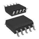
    AC DIMMER CONTROLLER FOR 50HZ / IGBT and MOSFET AC Phase Cut Dimmer Controller PMIC 10-SOIC #CommonPartsLibrary #PowerManagement #FL5150

    Properties

    Integrated Circuit

    ON Semiconductor

    FL5150MX

    U

    Pricing & Availability

    DPN

    Stock

    Qty 1

    2

    0

    $0.00

    3

    0

    $0.00

    1

    30

    $1.7606

    1

    6.8K

    $1.60

    3

    0

    $0.00

    Controls