Part Information Review and Update
3:55
Considering project updates.
Working.
Reviewing the bill of materials.
Analyzing the schematic.
Analyzing the PCB layout.
Searching web for: "Samtec ERF8-030-05.0-S-DV-L-K-TR datasheet PDF official Samtec"
Found 1 results.
Looking for "Extract mechanical details for ERF8-030-05.0-S-DV-L-K-TR including pin count, row count, terminal numbering, shield or weld tab information, and dimensions relevant to footprint verification." in erf8-xxx-xx.x-xxx-dv-xxxx-xx-mkt.pdf
Looking for "Extract the recommended PCB footprint details for ERF8-030-05.0-S-DV-L-K-TR including number of signal pads, shield/mechanical pads, pad pitch, row spacing, and any pad numbering conventions." in erf8-xxx-xx.x-x-dv-xxxx-tr-footprint.pdf
Looking for "Extract ordering code details for ERF8-030-05.0-S-DV-L-K-TR including number of positions, rows, lead style, plating, shield, packaging, and description." in erf8-s.pdf
Looking for "Extract key electrical and environmental specifications for ERF8 / ERM8 including current rating, voltage rating, operating temperature, insulation resistance, contact resistance, and dielectric withstanding voltage." in erm8-erf8.pdf
Analyzing the PCB layout.
Set Datasheet URL to "https://suddendocs.samtec.com..."
Set Datasheet URL to "https://suddendocs.samtec.com/productspecs/erm8-erf8.pdf"
- Existing project context had manufacturer and MPN set but no visible Datasheet URL in the live project properties inspected at runtime.
- I set the project Datasheet URL property to the official Samtec product specification PDF:
https://suddendocs.samtec.com/productspecs/erm8-erf8.pdf
Current Project Metadata
| Field | Current / observed value | Datasheet / official source check | Status |
|---|---|---|---|
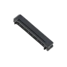
| Manufacturer Part Number | ERF8-030-05.0-S-DV-L-K-TR | Matches target part number | OK |
| Manufacturer Name | Samtec | Matches official source | OK |
| Designator Prefix | J | Appropriate for connector | OK |
| Datasheet URL | Set to official Samtec ERM8/ERF8 product spec | Official Samtec PDF | OK |
| Description | SAMTEC | Too generic; official description is a shielded/high-speed Edge Rate socket family | Mismatch / incomplete |
| Part Type | Not present at project level in visible properties | Should be Connector | Missing |
| Package / Case Code | Not present in visible project properties | Recommended: 0.80 mm Edge Rate socket, 2x30, vertical SMT, ERF8-S/DV-L or similar | Missing |
| Operating Voltage | Not present | 225 VAC rating from product spec | Missing |
| Max Current | Not present | 2.2 A current rating from product spec | Missing |
| Operating Temperature | Not present | -55°C to +125°C | Missing |
- ERF8 = shielded socket family / Edge Rate socket assembly.
- 030 = 30 positions per row.
- DV = double vertical, 2-row configuration.
- Total signal terminals = 60.
- Pitch = 0.80 mm.
- Lead style
05.0= 5 mm lead style. - L = 10 µin / 0.25 µm gold on contact, matte tin on tail.
- K = polyimide film pick-and-place pad.
- TR = tape-and-reel packaging.
S in different option positions. For this configured part, -S before -DV is associated with the shielded/high-speed socket family optioning in the ERF8-S catalog context; the mechanical extraction also noted possible ambiguity with plating/option field interpretation. The actual project should preserve the exact manufacturer MPN as the authority.Key Specifications
| Specification | Value |
|---|---|
| Connector series | ERF8 / ERM8 Edge Rate rugged high-speed socket / terminal strip |
| Connector type | Board-to-board socket / high-speed connector |
| Pitch | 0.80 mm |
| Positions per row | 30 |
| Rows | 2 |
| Total signal contacts | 60 |
| Current rating | 2.2 A |
| Voltage rating | 225 VAC |
| Dielectric withstanding voltage | 675 VAC |
| Insulation resistance | 50,000 MΩ |
| Contact resistance / LLCR requirement | Δ15 mΩ maximum |
| Operating temperature | -55°C to +125°C |
| Operating humidity | 90% to 95% per EIA-364-31 |
| Packaging | Tape & reel |
- The schematic contains 60 Terminal components, with terminal designators and
Pin Numberproperties covering 01 through 60. - Each terminal is a generic Flux terminal component with part UID
835bf3e1-33dd-41bb-a166-c0a31607d645. - Each terminal has:
Part Type: TerminalPin Type: PassiveDesignator Prefix: PPin Numbermatching its terminal number.
- 60 signal contacts = 2 rows × 30 positions.
- Numbering convention:
- Pin 1 at one end on one row.
- Pin 2 at the corresponding end on the other row.
- Odd-numbered pins on one row; even-numbered pins on the other row.
- Pin 59 / 60 at the opposite end.
- Pin count: OK — 60 terminals present, matching 60 signal contacts.
- Pin numbering: OK — terminals cover 01–60.
- Pin type: OK for a connector —
Passiveis suitable for connector contacts. - Pin descriptions: Missing — no
Pin Descriptionproperty is present on the terminals. For a connector, this is not necessarily fatal, but adding descriptions likeSignal contact 01throughSignal contact 60would improve library quality. - Symbol layout: Appears split left/right with odd/even ordering consistent with a two-row connector symbol. No electrical mismatch found.
- Layout tree contains 60 signal Pad nodes with designators
01through60. - Layout tree also contains additional mount/mechanical pad nodes:
S1S2- two pads with designator
None
- Assets include:
- Default symbol SVG.
- KiCad footprint asset:
SAMTEC_ERF8-030-05.0-S-DV-L-K-TR.kicad_mod. - STEP model:
ERF8-030-05.0-S-DV-L-K-TR.stp.
- 60 signal SMT pads.
- Signal pad size: 0.500 mm × 1.10 mm.
- Signal pad pitch: 0.80 mm.
- Two PCB rows, row spacing approximately 4.50 mm.
- For
-Loption:- 2 × Ø0.83 mm PTH mechanical/latch holes.
- 2 × Ø1.45 mm NPTH holes.
- No separate shield pads for this exact configured footprint; latches/mechanical holes are expected.
- Signal pad count: OK — 60 signal pads observed.
- Mechanical/latch features: Likely OK — observed
S1,S2, and twoNonepad nodes align with expected 2 PTH + 2 NPTH mechanical/latch features. - Pad numbering: Likely OK by count and designator coverage; exact physical ordering could not be fully verified from the layout
treeoutput because detailed pad coordinates/sizes were not exposed in the returned layout data. - 3D model: Present — STEP asset exists.
- Footprint asset: Present — KiCad footprint asset exists.
-
Project description is too generic
- Current description:
SAMTEC. - Recommended description:
0.80 mm Edge Rate high-speed board-to-board socket connector, 2x30 positions, vertical SMT, 2.2 A, 225 VAC, -55°C to +125°C.
- Current description:
-
Missing project-level metadata
- Recommended additions:
Part Type = ConnectorPackage or Case Code = ERF8 2x30 vertical SMT socket, 0.80 mm pitchOperating Voltage = 225 VMax Current = 2.2 AOperating Temperature = -55°C to +125°C
- Recommended additions:
-
Terminal pin descriptions are missing
- All 60 terminals have
Pin NumberandPin Type, but no pin descriptions. - Recommended: add concise descriptions like
Signal contact 01, etc., if desired.
- All 60 terminals have
-
Footprint geometry not fully verifiable from returned layout detail
- Count-level checks pass.
- Exact pad dimensions and coordinates should be visually/DRC verified against the official Samtec footprint drawing if final library release quality is required.
-
No BOM part entry appears in BOM output
- BOM query returned “No parts have been added yet,” which may be normal for a published part project but should be noted if expecting a conventional design BOM.


Welcome 👋
Flux accelerates your PCB design with AI.
Create your account to start using this component and bring your ideas to life.
