Treat Flux like your intern. Tell it what you'd like to build and it'll get to work. You can also ask it questions, brainstorm ideas, and teach it your preferences. Learn More
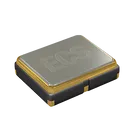
To wire a standard oscillator to a PIC32 microcontroller, you will typically follow these connections:
Connect the VDD pin of the oscillator to the VDD/VCC line of the PIC32 for power supply. This spherical voltage is dependent upon the specification of the oscillator and the microcontroller, and commonly used value is 3.3V.
Connect the GND pin of the oscillator to the GND (ground) line of the PIC32 to create a common ground.
Connect the OUTPUT pin of the oscillator to one of the oscillator input pins of the PIC32. Depending on the model of your PIC32, this could be OSC1, OSC2, or another similar pin.
The TRI_STATE pin (Enable/Disable) of the oscillator can be controlled from a GPIO pin of the PIC32 if you want to control the oscillator enable/disable feature programmatically, otherwise, you can pull it high (to always enable) or low (to disable) as per your requirements.
Now, these are just general connections and might differ based on the specific oscillator and PIC32 model you are using. The pin numbers might also vary.
Please note, you should configure the system oscillator settings in the PIC32 configuration bits to match the frequency of this external oscillator for correct operation.
Let me define these in terms of flux.ai hardware connections. Assuming your oscillator is labelled OSC and the PIC32 is labelled U1 connects as follows:
Connect OSC:VDD to U1:VDD
Connect OSC:GND to U1:GND
Connect OSC:OUTPUT to U1:OSC1 (Assuming you use OSC1 as the oscillator input pin, replace with the appropriate pin for your PIC32 model)
Connect OSC:TRI_STATE to either U1:some_GPIO (for programmable control) or directly to OSC:VDD (for always enabled) or OSC:GND (for disabled)
These are your basic connections needed for the oscillator to function with the PIC32.
The PIC32MZ0512EFE064 is a common microcontroller (MCU) with primary (primary oscillator/CLKI) and secondary (secondary oscillator/CLKO) oscillator ports. You can wire the oscillator to these pins. Here are the detailed connections:
Connect the VDD of the oscillator module to the 3.3V supply line of the PIC32MZ0512EFE064 for power supply.
Connect the GND of the oscillator to the ground (GND) of the PIC32MZ0512EFE064 for a common reference.
Connect the OUTPUT of the oscillator to the CLKI (input clock) of the PIC32MZ0512EFE064. This pin is also called OSC1 or POSC in the PIC32 datasheet.
Connect the TRI_STATE (Enable/Disable) of the oscillator to a GPIO (general purpose input/output) of the MCU if you want to control the oscillator enable/disable feature. By default, you can pull this pin HIGH to enable the oscillator.
In terms of the Flux design command, assuming your oscillator has a designator of OSC, and the MCU is U1, the following connections would be suitable:
Connect OSC:VDD to U1:3.3V (I'm assuming your 3.3V power line is marked as '3.3V'. If not, replace with your designator for the 3.3V power line)
Connect OSC:GND to U1:GND
Connect OSC:OUTPUT to U1:CLKI (or POSC, or the specific pin used for your primary input clock)
Connect OSC:TRI_STATE to U1:
Don't forget to set the system configuration of the MCU to match the oscillator frequency.
2y
Someone is typing...
2
TRI_STATE
VDD
GND
OUTPUT
No files yet
Reviews
Documents
Documents are markdown text files which describe project goals, capture details, or even simulation outputs.
drandall
copilot
drandall
copilot
OSC, and the MCU isU1, the following connections would be suitable: