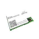
Part Review and Datasheet Verification
Thought for 4 sec
I’ll update each terminal with datasheet-based pin metadata: number, name/designator, type, functional group/section, and description, then verify the schematic properties.
Worked for 1 min 25 sec
Metadata was applied; I’m normalizing a few fields to Flux standard property names/options where possible while keeping the datasheet grouping intent.
Worked for 1 min 9 sec
Added datasheet-based metadata to all 22 E04-400M16S terminals and verified the updates. Each pin now has Pin Number, Pin Role/name, Pin Type, Pin Group, Section, and Pin Description; I used one primary group per pin and normalized pin types to Flux standard values where available.
Open items:
- The symbol is still represented as 22 separate Terminal components rather than one module component.
- SPI MISO/MOSI directions follow the EBYTE datasheet wording, which should be rechecked against host/module convention during integration.
Suggested next steps:
- Convert these terminals into a single 22-pin module symbol.
- Correct and verify the footprint pad coordinates against the official EBYTE package.
- Add VCC decoupling and RF/antenna layout constraints.
Fix symbol and footprint
Create module symbol
Fix footprint pads
Add support circuitry
Run design review
Name
Pin #
Type
Part Type
Pin Description
Pin Group
GND
1
Ground
Terminal
Ground wire; connect to power reference ground.
Ground
GND
2
Ground
Terminal
Ground wire; connect to power reference ground.
Ground
GND
3
Ground
Terminal
Ground wire; connect to power reference ground.
Ground
GND
4
Ground
Terminal
Ground wire; connect to power reference ground.
Ground
GND
5
Ground
Terminal
Ground wire; connect to power reference ground.
Ground
GPIO1
6
Bi-Directional
Terminal
Configurable general-purpose I/O port; see S2-LPQTR manual for details.
GPIO
GPIO2
7
Bi-Directional
Terminal
Configurable general-purpose I/O port; see S2-LPQTR manual for details.
GPIO
GPIO3
8
Bi-Directional
Terminal
Configurable general-purpose I/O port; see S2-LPQTR manual for details.
GPIO
VCC
9
Power In
Terminal
Power supply input, 2.5–3.6 V; ceramic filter capacitor recommended near VCC/GND.
Power
GND
10
Ground
Terminal
Ground wire; connect to power reference ground.
Ground
GND
11
Ground
Terminal
Ground wire; connect to power reference ground.
Ground
GND
12
Ground
Terminal
Ground wire; connect to power reference ground.
Ground
GPIO0
13
Bi-Directional
Terminal
Configurable general-purpose I/O port; see S2-LPQTR manual for details.
GPIO
SDN
14
Input
Terminal
Shutdown control input; see S2-LPQTR manual for detailed behavior.
Control
NC
15
Not Connected
Terminal
No connect; leave unconnected unless otherwise directed by manufacturer documentation.
No Connect
MISO
16
Input
Terminal
SPI data input pin per EBYTE datasheet wording; verify host/module direction convention during system schematic integration.
SPI
MOSI
17
Output
Terminal
SPI data output pin per EBYTE datasheet wording; verify host/module direction convention during system schematic integration.
SPI
SCLK
18
Input
Terminal
SPI clock input.
SPI
E04-400M16S