Compact Motor Driver Design

Work completed
  • Project description updated to “Ultra-Compact 4-Motor DRV8833 Breakout Board for Reliable Motor Control.”
  • System Architecture mermaid diagram added to project property.
  • Support components placed and configured:
    • D1–D4 TVS diodes
    • C1–C8 decoupling/bulk capacitors (0.1 µF & 10 µF)
    • R1–R6 sense and pull-up resistors
  • Connectors added:
  • Net wiring done per plan:
    • VM & GND to decoupling capacitors and DRV8833 VM/GND
    • VINT decoupling and pull-ups on nSLEEP/nFAULT
    • Sense resistors on AISEN/BISEN nets
    • Logic header pins wired to AINx/BINx
    • Motor connectors wired to AOUTx/BOUTx
Tasks not yet done
  • Place and configure the two DRV8833CPWPR motor driver ICs (DRV8833CPWPR).
Tasks I cannot perform
  • Generating a standalone mermaid diagram code block (plan 1.2).
  • Footprint verification and assignment for all components (plan 5.1).
  • Measuring and updating board extents and dimensions (plans 5.2.1–5.2.3).
  • Adding board margin, outline, and mounting holes (plans 5.3–5.4).
  • Classifying nets and setting layout rules (plan 6.1).
Success criteria review
  • Schematic with two DRV8833 ICs and all support components: ❌ DRV8833 ICs not yet placed.
  • All motor, logic, and power connectors exposed and wired: ✅
  • Final layout optimized and passing DRC/ERC: ❌ Layout not begun.
Recommended next step
Add the two DRV8833CPWPR ICs to the schematic, assign their pins, and wire them to the existing connectors and support components. Once the drivers are placed, we can finalize the schematic and move on to PCB footprint assignment and layout.
NC
BIN1
C3
Capacitance
100 nF
C5
Capacitance
100nF
R1 P2 - R3 P2
NSLEEP
VINT
NFAULT
AIN1
AOUT1
C8
Capacitance
10uF
GND
GND
GND
GND
C2
Capacitance
100 nF
R1 P2 - R3 P2
BOUT2
BIN2
BOUT1
BISEN
GND
AOUT2
GND_1
C4
Capacitance
100 nF
AIN2
C6
Capacitance
100nF
GND_2
C7
Capacitance
10uF
VM
C1
Capacitance
100 nF
AISEN
D3
J2
R4
Resistance
100 Ω
D2
R2
Resistance
100 Ω
J5
R3
Resistance
100 Ω
J3
J4
J1
D1
R5
Resistance
10kΩ
D4
R1
Resistance
100 Ω
J6
R6
Resistance
10kΩ

No files yet

Documents

    Documents are markdown text files which describe project goals, capture details, or even simulation outputs.

    Assets

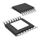
    DRV8833CPWPR-thumb.png

    DRV8833CPWPR-thumb.png

    DRV8833CPWPR-thumbThumbnail
    svg

    DRV8833CPWPR

    DRV8833CPWPR Symbol.svgDefault
    DRV8833CPWPR.stp

    DRV8833CPWPR.stp

    3D_DRV8833CPWPR3D Model
    kicad_mod

    SOP65P640X120-17N.kicad_mod

    SOP65P640X120-17NFootprint

    DRV8833CPWPR

    DRV8833CPWPR thumbnail
    Dual DRV8833 Quad Motor Driver Carrier – Power, Logic, and Motor Interconnect Overview

    Properties

    Texas Instruments

    Diagram


    ""Power Input"" ""Logic IO"" ""DRV8833_A"" ""DRV8833_B"" ""Motor Outputs"" VM Input Connector GND Reference Logic Header AIN1_A AIN2_A BIN1_A BIN2_A AIN1_B AIN2_B BIN1_B BIN2_B NSLEEP NFAULT VINT DRV8833 A AOUT1_A AOUT2_A BOUT1_A BOUT2_A AISEN_A BISEN_A VINT_A VM_A GND_A DRV8833 B AOUT1_B AOUT2_B BOUT1_B BOUT2_B AISEN_B BISEN_B VINT_B VM_B GND_B M1 Connector M2 Connector M3 Connector M4 Connector

    IC

    DRV8833CPWPR

    SOP65P640X120-17N

    Integrated Circuit

    Pricing & Availability

    DPN

    Stock

    Qty 1

    5

    0–346K

    $0.8431–$1.8976

    1

    2K

    $1.12668

    1

    296

    $1.18071

    1

    2.3K

    $1.8709

    1

    2.7K

    $2.24

    3

    71–2K

    $1.4443–$1.903

    Controls