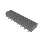
Part Review and Datasheet Update
Thought for 1 min
I found the official Samtec CLT series datasheet and recorded it in the project metadata available to me; now I’m checking the part details against it.
Worked for 3 mins 56 sec
Completed the part review for Samtec CLT-108-02-L-D-A and saved the detailed findings in Part Review: Samtec CLT-108-02-L-D-A.
Open items:
- A true
Datasheet URLproject property was not exposed by the available metadata editor, so I recorded the official Samtec datasheet URL inImplementation Details. - Pin count and passive terminals match the datasheet; exact footprint pad dimensions and pin-number orientation could not be fully machine-verified from the returned layout/datasheet text.
- Current description is too generic: “SAMTEC”.
Suggested next steps:
- Add/update a canonical Datasheet URL property in the part editor if available.
- Replace the description with a full connector description.
- Add clearer per-pin descriptions or row grouping once Samtec pin-number orientation is visually confirmed from the drawing.
Fix metadata and verify
Update part description
Add pin descriptions
Run design review
Check official footprint
Refine this doc
Ask about this doc
Part Review: Samtec CLT-108-02-L-D-A
Existing Flux Part Metadata
- Project/part name: CLT-108-02-L-D-A
- Manufacturer: Samtec
- Manufacturer Part Number: CLT-108-02-L-D-A
- Description: SAMTEC
- Published part UID: f8243eb5-823e-40dd-b0bf-2b15e35567ac
- Pads / terminals in project: 16
- Existing explicit Datasheet URL property: not exposed in current project metadata returned by inspection
- Datasheet recorded in available metadata:
Implementation Details = Datasheet: https://suddendocs.samtec.com/catalog_english/clt.pdf
Official Datasheet / Source Documents
- Samtec product page: https://www.samtec.com/products/clt-108-02-l-d-a
- Samtec CLT catalog/datasheet: https://suddendocs.samtec.com/catalog_english/clt.pdf
- Samtec mechanical drawing: https://suddendocs.samtec.com/prints/clt-1xx-02-xx-d-xx-x-xx-mkt.pdf
Key Datasheet Specs
- Series: CLT, low-profile dual-wipe socket strip
- Pitch: 2.00 mm / 0.0787 in
- Positions: 8 positions per row (
108ordering code) - Rows: double row (
-D) - Total contacts: 16
- Lead style:
-02= surface mount - Plating:
-L= 10 µin / 0.25 µm gold on contact, matte tin on tail - Option:
-A= alignment pin; 8 positions satisfies the minimum for molded or staked alignment pins - Orientation: vertical
- Contact system: Tiger Claw dual-wipe
- High-speed rating: up to 8 Gbps NRZ per Samtec product page
- Coplanarity: 0.10 mm / 0.004 in max for 02–25 positions; applies to this 8-position part
- Nominal overall length for 8 positions: 16.00 mm ±0.20 mm
- First-to-last contact span: 14.00 mm reference
- Body width reference: 4.00 mm
- Height reference: 2.12 mm
- Alignment-pin spacing for
-A: 12.00 mm reference
Symbol Cross-Check
The schematic symbol contains 16 terminal components with pin numbers 01 through 16. This matches the datasheet-derived total contact count for CLT-108-02-L-D-A: 8 positions per row × 2 rows = 16 contacts.
All terminal pin types are Passive, which is appropriate for a socket/header connector.
Observed symbol placement alternates odd pins on the left and even pins on the right:
- Left side: 01, 03, 05, 07, 09, 11, 13, 15
- Right side: 02, 04, 06, 08, 10, 12, 14, 16
This is a common and reasonable dual-row connector symbol convention. The searchable datasheet content did not expose an explicit pin-numbering diagram, so I could not conclusively verify the odd/even row orientation against Samtec’s drawing.
Footprint Cross-Check
The PCB footprint contains:
- 16 electrical pads named 01 through 16
- 2 additional unnumbered mount/alignment pads under the footprint mounts container
- Silkscreen/body outline approximately 16.5 mm long by 6.42 mm high in the rendered footprint
- Contact/body features consistent with a 16-contact dual-row SMT socket
This aligns with the datasheet requirements for a 16-contact SMT CLT connector with the
-A alignment-pin option. The two unnumbered mount pads are consistent with alignment pins.The extracted layout tree did not expose pad geometry/coordinates, so pad sizes, exact row spacing, and alignment-hole diameters could not be numerically verified from the project data returned. The visible silkscreen length is close to the 16.00 mm nominal body length from the drawing.
Pin Descriptions / Properties Cross-Check
Each terminal has:
- Pin Number set correctly from 01 to 16
- Pin Type = Passive
- Part Type = Terminal
- No meaningful per-pin Pin Description property beyond the pin number
For this connector, generic passive terminal descriptions are acceptable. If higher-quality part metadata is desired, each pin could be described as “Socket contact 01”, “Socket contact 02”, etc., or grouped by row if Samtec pin-number orientation is confirmed from the non-searchable drawing graphics.
Mismatches / Issues Flagged
- Datasheet URL property missing or inaccessible: Inspection did not show a dedicated Datasheet URL property. I recorded the official datasheet URL in the available project metadata field
Implementation Details, but this is not equivalent to a canonical Datasheet URL property. - Part description too generic: Current description is only “SAMTEC”. Recommended description: “Samtec CLT-108-02-L-D-A, 2.00 mm pitch low-profile dual-wipe SMT socket, 8 positions per row, dual row, 16 contacts, alignment pins.”
- Pin descriptions are minimal: Pins are numbered correctly and passive, but no descriptive text is present.
- Footprint geometry not fully machine-verifiable from returned layout data: Pad coordinates/sizes and alignment-hole details were not exposed by the layout inspection response, so exact land pattern dimensions could not be fully checked.
- Pin numbering orientation not conclusively verified: The symbol has all 16 pin numbers and a sensible odd/even arrangement, but the scraped datasheet text did not include an explicit pin-numbering graphic to confirm orientation.
Overall Assessment
The part appears broadly consistent with the official Samtec CLT-108-02-L-D-A configuration: 16 passive terminals, dual-row 2.00 mm SMT connector, and footprint support for the
-A alignment pin option. The main improvements are metadata completeness: add a true Datasheet URL property if available in the part editor, expand the description, and add clearer pin descriptions.Existing Flux Part Metadata
Official Datasheet / Source Documents
Key Datasheet Specs
Symbol Cross-Check
Footprint Cross-Check
Pin Descriptions / Properties Cross-Check
Mismatches / Issues Flagged
Overall Assessment