Part Metadata Review and Validation
4:07
Analyzing the schematic.
Reviewing the bill of materials.
Analyzing the PCB layout.
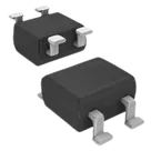
Looking for "product description and package information" in 325909.pdf
Looking for "absolute maximum ratings" in 325909.pdf
Looking for "electrical characteristics" in 325909.pdf
Looking for "recommended operating conditions" in 325909.pdf
Looking for "pin configuration and pin descriptions" in 325909.pdf
Looking for "mechanical dimensions MBS-2 package" in 325909.pdf
Looking for "features" in 325909.pdf
Looking for "CDBHM260L-HF specific reverse voltage value in part number table" in 325909.pdf
Looking for "package diagram with terminal labels AC plus minus and pin numbering for MBS-2" in 325909.pdf
Looking for "top view bottom view orientation markings for MBS-2 bridge rectifier" in 325909.pdf
Looking for "mechanical drawing identify which pads are on left and right and spacing values for MBS-2" in 325909.pdf
Looking for "CDBHM260L-HF reverse voltage in table" in 325909.pdf
Looking for "MBS-2 package pin numbering and polarity marks" in 325909.pdf
Evalu.
Considering.
1) Available part information in the project
2) Datasheet status
| Check | Result |
|---|---|
| Datasheet already set? | Yes |
| Web lookup needed? | No |
| Action needed to add/update datasheet property? | No |
3) Datasheet summary
| Category | Extracted metadata |
|---|---|
| Product family | Low VF SMD Schottky bridge rectifiers |
| Specific device | CDBHM260L-HF |
| Package | MBS-2 |
| Reverse voltage | VRRM = 60 V |
| RMS voltage | Family table includes VRMS values by variant; the 60 V variant corresponds to the device family position for CDBHM260L-HF |
| DC blocking voltage | VDC = 60 V |
| Average forward rectified current | I(AV) = 2.0 A @ TL = 100 °C |
| Peak forward surge current | IFSM = 50 A |
| Forward voltage | VF = 0.70 V at 2.0 A DC |
| Reverse current | IR = 1.0 mA @ TJ = 25 °C, 20 mA @ TJ = 100 °C |
| Junction capacitance | Datasheet extract returned CJ = 125 pF in one result and a family table extract also included 80 pF; this looks like a family-table ambiguity and should be read directly from the original PDF before publishing final parametrics |
| Thermal resistance | Datasheet extract returned RθJA = 20 °C/W; another family-table extract included multiple values, so use 20 °C/W unless manually verified otherwise from the PDF |
| Operating temperature | -55 to +125 °C |
| Storage temperature | -55 to +150 °C |
| Mechanical notes | Molded plastic case, polarity indicated on package, approx. 0.125 g, reel 3000 pcs, reel size 13 in |
| Features | Surface mount, metal-semiconductor junction with guarding, very low forward voltage drop, epitaxial construction, Pb-free, halogen-free, UL 94V-0 plastic, high current capability |
4) Absolute maximum / operating data
| Parameter | Value |
|---|---|
| VRRM | 60 V |
| VDC | 60 V |
| I(AV) | 2.0 A |
| IFSM | 50 A |
| VF | 0.70 V @ 2.0 A |
| IR | 1.0 mA @ 25 °C, 20 mA @ 100 °C |
| TJ | -55 to +125 °C |
| TSTG | -55 to +150 °C |
5) Pin / terminal information
| Project terminal | Project pin number | Intended function from symbol | Datasheet evidence |
|---|---|---|---|
| ~_1 | 1 | AC input | Datasheet confirms standard bridge-rectifier arrangement in MBS-2 package |
| ~_2 | 2 | AC input | Datasheet confirms standard bridge-rectifier arrangement in MBS-2 package |
| 3 | Positive DC output | Datasheet polarity mark includes + | |
| - | 4 | Negative DC output | Datasheet polarity mark includes - |
- Overall body dimensions include 7.0 mm max and widths around 4.2 mm, 4.5 mm, 4.9 mm
- Lead / terminal related dimensions include 0.15 mm, 0.35 mm, 0.50 mm, 0.80 mm
- Additional outline values include 0.7 mm, 0.9 mm, 1.1 mm, 1.3 mm, 1.7 mm, 2.3 mm, 2.7 mm
- Chamfer callout: 0.5 mm x 45°
7) Cross-check of symbol and footprint vs datasheet
| Check | Result | Risk |
|---|---|---|
| Pin count | Pass: project has 4 terminals and footprint has 4 pads | Low |
| Package family | Pass: project description says MBS-2, datasheet says MBS-2 | Low |
| Polarity presence | Pass: project symbol exposes + and -, datasheet marks polarity on package | Low |
| AC terminals present | Pass: project symbol exposes two AC terminals, ~_1 and ~_2 | Low |
| Explicit pin descriptions | Weak: project pins are generic terminals with undefined pin names beyond symbol labels | Medium |
| Pin-type metadata | Weak: all four project terminals are marked Pin Type: Unspecified | Medium |
| Footprint pad geometry | Not fully verifiable from available layout metadata; only pad existence was exposed, not exact pad sizes / spacing | Medium |
| Pin-number-to-physical-pad mapping | Not fully proven from tool-visible geometry; project uses mapping 1= | Medium |
8) Mismatches / issues to flag
| Issue | Why it matters | Severity |
|---|---|---|
| Generic symbol metadata instead of explicit bridge-rectifier pin descriptions | Can cause ambiguity during reuse, export, or later library QA | Medium |
| Pin types left as Unspecified | Reduces ERC quality and can hide mistakes in downstream designs using this part | Medium |
| Footprint dimensions not fully validated against labeled datasheet drawing | A wrong MBS-2 land pattern could cause assembly failure or solderability issues | High if unverified |
| Datasheet extraction ambiguity on some family-table values like CJ and RθJA | Could lead to incorrect structured properties if copied blindly into the part metadata | Medium |
- The part project is mostly consistent with the datasheet at a high level: 4 pins, bridge rectifier, MBS-2, polarity outputs present.
- I do not see an obvious symbol-level polarity reversal.
- The main remaining manufacturing risk is that the footprint geometry and exact pad mapping are not fully validated from the metadata currently exposed.
- The main library-quality issues are:


Welcome 👋
Flux accelerates your PCB design with AI.
Create your account to start using this component and bring your ideas to life.
