Part Information Review and Update
2:43
Consulting on project sync.
Reviewing the bill of materials.
Analyzing the schematic.
Analyzing the PCB layout.
Looking for "For BM03B-ACHSS-GAN-TF (LF)(SN), extract the official datasheet/product specifications: manufacturer, full part number, series, connector type, mounting style, orientation, pitch, number of positions, current rating, voltage rating, applicable wire size, mating connector or applicable socket, operating temperature, package/footprint mechanical details, pin/contact numbering or terminal count." in ach_8
Looking for "For BM03B-ACHSS-GAN-TF (LF)(SN), extract mechanical footprint details including number of signal contacts, solder tabs/metal fittings, recommended PCB layout dimensions, pitch, and whether mechanical pads are electrical pins." in ach_8
Reviewing project properties.
BM03B-ACHSS-GAN-TF (LF)(SN) part project: project properties, description, schematic terminals/symbol, PCB footprint pads, and attached assets. The project already has a Datasheet URL set to https://www.jst.fr/en/product/ach_8, so no web-search/update was required.Project metadata
| Field | Current value | Review |
|---|---|---|
| Manufacturer Part Number | BM03B-ACHSS-GAN-TF (LF)(SN) | Matches requested JST part number format. |
| Manufacturer Name | JST | OK. |
| Part Type | Connectors | OK, though singular Connector may be cleaner if using normalized library metadata. |
| Designator Prefix | J | OK for connector. |
| Mount | Surface Mount | OK. |
| Datasheet URL | https://www.jst.fr/en/product/ach_8 | Present; no update needed. |
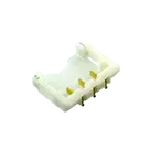
| Description | Connector Header Surface Mount, Right Angle 3 position 0.047" (1.20mm) | Mismatch: datasheet/product information indicates top-entry/straight SMT header, not right-angle. |
Assets
| Asset | Type | Role |
|---|---|---|
BM03B-ACHSS-GAN-TF.STEP | STEP | 3D model |
BM03BACHSSGANTFLFSN.kicad_mod | KiCad footprint | Default footprint asset |
BM03B-ACHSS-GAN-TF__LF__SN_ Symbol.svg | SVG | Default symbol/thumbnail |
Schematic symbol / terminals found
| Terminal designator | Pin Number property | Pin Type | Assessment |
|---|---|---|---|
1 | 1 | Unspecified | Signal/contact pin present; should be described as circuit/contact 1. |
2 | 2 | Unspecified | Signal/contact pin present; should be described as circuit/contact 2. |
3 | 3 | Unspecified | Signal/contact pin present; should be described as circuit/contact 3. |
MP1 | MP1 | Unspecified | Mechanical solder tab/pad present; OK if footprint has matching pad, but should be clearly described as mechanical/non-signal. |
MP2 | MP2 | Unspecified | Mechanical solder tab/pad present; OK if footprint has matching pad, but should be clearly described as mechanical/non-signal. |
1, 2, 3, MP1, and MP2, matching the schematic terminals. This is consistent with a 3-circuit connector plus two mechanical solder tabs.Datasheet / official product information extracted
| Spec | Official value found |
|---|---|
| Manufacturer | JST / J.S.T. Mfg. Co. |
| Series | ACH |
| Connector type | Wire-to-board connector/header |
| Mounting style | SMT / surface mount |
| Orientation | Top-entry / straight SMT header |
| Pitch | 1.2 mm |
| Positions / circuits | 3 |
| Electrical contacts | 3 contacts / circuits |
| Mechanical solder tabs | Present, separate from contacts |
| Current rating | 2 A AC/DC for 1–3 circuits with AWG #28 |
| Voltage rating | 50 V AC/DC |
| Operating temperature | −25 °C to +85 °C, including temperature rise from applied current |
| Contact resistance | 10 mΩ max initial; 20 mΩ max after environmental tests |
| Insulation resistance | 100 MΩ min |
| Withstanding voltage | 500 VAC/minute |
| Applicable housing | ACHR-03V-S for 3 circuits |
| Applicable crimp contacts | SACH-003G-P0.2 / SACH-003G-P0.2B |
| Wire size | AWG #32 to #28 overall ACH range; contact variants cover AWG 32–30 and AWG 30–28 |
| Body / mechanical | Low-profile; approx. 1.4 mm height, 4.3 mm width/depth; BM03B A = 2.4 mm, B = 5.4 mm |
| Recommended PCB pattern | 1.2 mm pitch, 3-contact span 2.4 mm; pattern viewed from connector mounting side; pitch tolerance ±0.05 mm non-accumulating |
BM03B-ACHSS-GAN-TF (LF)(SN) matches the JST ACH 3-position SMT header family, and the manufacturer property is JST.3-position JST ACH wire-to-board SMT top-entry header, 1.2 mm pitch, 2 A, 50 V
1, 2, 3 plus MP1, MP2 mechanical solder tabs. This is acceptable for a part footprint if the mechanical solder tabs are intentionally exposed as footprint pads, but they should not be treated as signal contacts.Table
| Terminal | Recommended Pin Type | Recommended Pin Description |
|---|---|---|
1 | Passive | Contact circuit 1 |
2 | Passive | Contact circuit 2 |
3 | Passive | Contact circuit 3 |
MP1 | Passive or Unspecified | Mechanical solder tab |
MP2 | Passive or Unspecified | Mechanical solder tab |
1, 2, 3, MP1, and MP2, matching the symbol terminals. This aligns with 3 electrical contacts plus two mechanical solder tabs. A geometry-level check confirms only the pad names/counts from Flux metadata; exact pad dimensions should be visually or mechanically verified against the JST recommended PCB pattern if needed.Pin Type: Unspecified and no concise Pin Description properties. For a connector, the three electrical contacts should generally be Passive; mechanical pads may remain Unspecified or be marked Passive with clear mechanical descriptions.Table
| Suggested property | Suggested value |
|---|---|
| Package or Case Code | ACH 3-position SMT top-entry header, 1.2 mm pitch |
| Operating Voltage | 50 V |
| Max Current | 2 A |
| Operating Temperature | -25°C to +85°C |
| Implementation Details | Mates with ACHR-03V-S housing; use SACH-003G-P0.2 or SACH-003G-P0.2B contacts; MP1/MP2 are mechanical solder tabs, not signal contacts. |
- Description orientation mismatch: current description says
Right Angle; official data saysTop-entry / straight SMT. - Pin typing incomplete: pins
1,2,3,MP1, andMP2are allUnspecified. - Pin descriptions missing: no terminal-level functional descriptions are set.
- Mechanical pads need clearer treatment:
MP1andMP2are present and footprint-matched, but should be documented as mechanical solder tabs, not electrical circuits. - Useful electrical/mechanical properties missing: current rating, voltage rating, operating temperature, and package/case information are not set as project properties.
- Update project description to:
3-position JST ACH wire-to-board SMT top-entry header, 1.2 mm pitch, 2 A, 50 V - Set pin/contact terminal types and descriptions:
1: Passive,Contact circuit 12: Passive,Contact circuit 23: Passive,Contact circuit 3MP1: Passive or Unspecified,Mechanical solder tabMP2: Passive or Unspecified,Mechanical solder tab
- Add project properties for current rating, voltage rating, operating temperature, package/case, and implementation details using the exact existing/default property names where available.
- Optionally perform a detailed footprint geometry audit against the JST recommended PCB pattern drawing before publishing/reusing this part in production designs.


Welcome 👋
Flux accelerates your PCB design with AI.
Create your account to start using this component and bring your ideas to life.
