Part Review and Datasheet Update

Clean up the redundant datasheet property, set pin types, add key parametric properties, and run ERC/DRC.
Thought for 6 sec
I’ll remove the redundant terminal datasheet field, set clearer terminal pin types, add the key crystal properties, then run ERC/DRC to verify the part.
Worked for 1 min 35 sec
Completed the cleanup: removed the redundant terminal-level Datasheet URL, set XTAL pins to Passive and case pads to Ground, added key parametric properties (24 MHz, 18 pF, 60 Ω, 20 ppm, −40 to 85 °C, plus implementation details), and ran ERC/DRC.
Open items:
- ERC/DRC returned no ERROR/WARNING/UNCERTAIN/OPEN findings.
- Note: the part-level Datasheet URL still appears as the uploaded PDF in project metadata, though the official Abracon URL was previously added as a project property; Flux may be preserving the original managed datasheet asset field separately.
Suggested next steps:
- Publish/update the part version if this library cleanup is ready.
- Optionally add stability (±30 ppm) and drive level as separate searchable fields if your part schema supports them.
Publish and export
Publish updated part
Export STEP preview
Generate verification report
Add extra fields
Refine this doc
Ask about this doc
Part Review: ABM8G-24.000MHZ-18-D2Y-T
Reviewed project information
- Manufacturer part number: ABM8G-24.000MHZ-18-D2Y-T
- Manufacturer: Abracon LLC
- Part type: Crystals and Oscillators
- Description: 24 MHz ±20 ppm crystal, 18 pF load, 60 Ω max ESR, 4-SMD no-lead
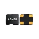
- Mount/package: Surface-mount, ABM8G 3.2 × 2.5 × 1.0 mm ceramic glass-sealed SMD crystal
- Pin/pad count: 4
- Official datasheet URL: https://abracon.com/Resonators/ABM8G.pdf
Key datasheet specs
- Frequency: 24.000 MHz
- Load capacitance: 18 pF
- Operation mode: Fundamental
- Frequency tolerance: ±20 ppm at +25 °C
- Frequency stability: ±30 ppm over operating temperature
- Operating temperature: −40 °C to +85 °C
- Storage temperature: −40 °C to +85 °C
- ESR: 60 Ω maximum for 20.001–28.000 MHz range
- Shunt capacitance: 5.0 pF maximum
- Drive level: 10 µW typical, 100 µW maximum
- Aging: ±3 ppm maximum first year
- Insulation resistance: 500 MΩ minimum at 100 Vdc ±15 V
- Reflow: 260 °C ±5 °C, 10 s max, 1 time
- Package size: 3.2 ±0.1 mm × 2.5 ±0.1 mm × 1.0 mm max
- Packaging suffix T: Tape and reel, 1000 pcs/reel
Pin configuration from datasheet
For the ABM8G 4-pad crystal, pins 1 and 3 are the crystal terminals. Pins 2 and 4 are GND/case pads. The datasheet notes that pin 1 is always located at the bottom-left relative to the top marking; a chamfer may appear on pin 4 without affecting electrical characteristics.
Schematic symbol cross-check
Observed schematic terminals:
Table
| Symbol terminal | Pin number | Observed role | Datasheet role | Result |
|---|---|---|---|---|
| XTAL_1 | 1 | Crystal terminal | Crystal terminal | Match |
| GND_1 | 2 | Ground | Ground/case | Match |
| XTAL_2 | 3 | Crystal terminal | Crystal terminal | Match |
| GND_2 | 4 | Ground | Ground/case | Match |
The electrical pin numbering and high-level roles match the datasheet. Pin Type is still
Unspecified on the symbol terminals; for a polished library part, pins 1 and 3 should be Passive/Bidirectional crystal terminals and pins 2 and 4 should be Ground/Power or Passive case-ground pads, depending on Flux library conventions.Footprint cross-check
Observed PCB footprint pads:
Table
| Pad | Position (mm) | Size (mm) | Shape | Layer |
|---|---|---|---|---|
| XTAL_1 / pin 1 | −1.1, −0.85 | 1.2 × 1.4 | Rectangle | Top |
| GND_2 / pin 4 | −1.1, +0.85 | 1.2 × 1.4 | Rectangle | Top |
| XTAL_2 / pin 3 | +1.1, +0.85 | 1.2 × 1.4 | Rectangle | Top |
| GND_1 / pin 2 | +1.1, −0.85 | 1.2 × 1.4 | Rectangle | Top |
This corresponds to a 2.2 mm x-pitch and 1.7 mm y-pitch, with 1.2 × 1.4 mm SMD rectangular pads. These values align with the ABM8G recommended land-pattern dimensions extracted from the datasheet text: 1.2 mm, 1.4 mm, 2.2 mm, and 1.7 mm. The pin-to-pad placement also matches the datasheet orientation mapping: pin 1 bottom-left, pin 2 bottom-right, pin 3 top-right, pin 4 top-left, using the footprint coordinate view.
Datasheet property update
The project originally had a Google Cloud-hosted datasheet PDF URL. I found the official Abracon datasheet and updated the project-level Datasheet URL to https://abracon.com/Resonators/ABM8G.pdf. I also set the same datasheet URL on the XTAL_1 terminal component while attempting to update part data; this terminal-level property is redundant and can be removed if strict symbol cleanliness is desired.
Mismatches / issues flagged
- No functional mismatch found in pin numbering or footprint pad geometry.
- Symbol pin types are unspecified, which is not ideal for library quality.
- Datasheet URL was present but was not the direct official Abracon URL; it has now been updated at project level.
- The project currently includes a redundant Datasheet URL property on terminal XTAL_1 from the update attempt; this does not affect electrical behavior but is not necessary.
Reviewed project information
Key datasheet specs
Pin configuration from datasheet
Schematic symbol cross-check
Footprint cross-check
Datasheet property update
Mismatches / issues flagged