Treat Flux like your intern. Tell it what you'd like to build and it'll get to work. You can also ask it questions, brainstorm ideas, and teach it your preferences. Learn More
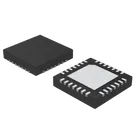
OUT1A is one of the output pins of the A4988 Stepper Motor Driver IC. This pin, along with OUT1B, serves to control one winding of a bipolar stepper motor.
When the IC is enabled and depending on the direction (DIR) and step signals (STEP), current is sent through OUT1A and OUT1B in a specific sequence. This generates a magnetic field in the coils of the motor and causes the shaft to rotate step by step.
Bear in mind, the output pins connect to the coils of the stepper motor and the polarity of the voltage applied to these pins defines the direction of the current flow through the winding, which in turn determines the direction of the magnetic field and thus, the direction of stepping.
Remember to connect the stepper motor to these outputs observing the correct polarity and coil pairings.
2y
Someone is typing...
2
OUT1B
SENSE2
~SLEEP
VCP
STEP
VBB2
~ENABLE
VBB1
MS1
VREG
ROSC
CP2
REF
OUT2A
VDD
CP1
DIR
OUT1A
MS2
OUT2B
~RESET
MS3
PAD
GND1
SENSE1
GND2
No files yet
Reviews
Documents
Documents are markdown text files which describe project goals, capture details, or even simulation outputs.
hseinreda89
hseinreda89
copilot
OUT1Ais one of the output pins of the A4988 Stepper Motor Driver IC. This pin, along withOUT1B, serves to control one winding of a bipolar stepper motor.DIR) and step signals (STEP), current is sent throughOUT1AandOUT1Bin a specific sequence. This generates a magnetic field in the coils of the motor and causes the shaft to rotate step by step.