Part Information Review and Correction
Thought for 1 min 39 sec
Review of available part information
Project metadata
Symbol / logical pin inventory
Datasheet URL status
Electrical characteristics
Environmental / materials
Recommended operating / durability information
Pin description status
Special features called out
Cross-check: symbol and footprint vs datasheet
What matches
Issues / risks found
Important nuance on pad spacing
Recommended fixes
Table
| Field | Value |
|---|---|
| Part | A-DS 09 PP/Z |
| Manufacturer | ASSMANN WSW components GmbH |
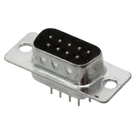
| Description | ASSMANN WSW A-DS Series, 9 Way Through Hole PCB D-sub Connector Plug, 2.77 mm Pitch |
| Mount | Through Hole |
| Part Type | Connector |
| MPN | A-DS 09 PP/Z |
| Designator Prefix | J |
| Datasheet |
Table
A datasheet URL is already set on this part, so no @web search or property update was needed.
Datasheet scan summary
General description
Table
| Item | Datasheet result |
|---|---|
| Product family | D-sub PCB connector |
| Quality class | Standard quality class III |
| Mounting style | Through-hole PCB mount |
| Available contact counts in family | 9 / 15 / 25 / 37 / 50 |
| Contact style family coding | Male / female variants exist |
Table
| Parameter | Datasheet value |
|---|---|
| Current rating | 3 A |
| Voltage rating | 250 V AC rms, 60 Hz |
| Contact resistance | 20 mΩ max at 1 A DC |
| Insulation resistance | 1000 MΩ at 500 VDC |
| Withstand voltage | 1000 V AC rms, 60 Hz, 1 minute |
Table
| Parameter | Datasheet value |
|---|---|
| Operating temperature | -20 °C to +105 °C |
| Insulator material | Glass-filled thermoplastic PBT |
| Flammability | UL94V-0 |
| Storage temperature | Not found in the PDF |
Table
| Parameter | Datasheet value |
|---|---|
| Recommended operating temperature | -20 °C to +105 °C |
| Mating cycles | Not found |
| Insertion force | Not found |
| Withdrawal force | Not found |
Table
| Item | Result |
|---|---|
| Individual functional pin descriptions | Not provided |
| Contact numbering | Numeric contacts only |
| Mechanical holes | Two shell / mounting holes provided |
For this connector, the datasheet behaves like a mechanical connector drawing rather than an IC datasheet, so there are no per-pin electrical functions beyond contact numbering.
Package / mechanical dimensions for 9-position version
Table
| Dimension | Datasheet value |
|---|---|
| A | 30.81 mm |
| B | 24.99 mm |
| C | 16.92 mm |
| E | 11.08 mm |
| F | 19.20 mm |
| Contact spacing in row | 2.77 mm |
| Row offset / spacing shown in layout drawing | 2.84 mm |
| Shell mounting hole | Ø3.05 clear hole |
| Recommended signal-hole size | Ø1.0 ±0.05 |
| Recommended mounting-hole size | Ø3.1 +0.05 / 0 |
Table
| Feature | Datasheet evidence |
|---|---|
| Through-hole D-sub connector | Yes |
| Family supports multiple pin counts | Yes |
| Standard class III connector | Yes |
| Flame-retardant insulator | Yes |
| Mechanical PCB layout drawing included | Yes |
Table
Table
| Area | Severity | Finding | Why it matters |
|---|---|---|---|
| Signal-hole drill size | High | Footprint uses 1.15 mm drill for pins 1-9, while the datasheet calls out Ø1.0 ±0.05 recommended PCB holes | Could produce excessive hole clearance, weaker solder fillets, poorer pin retention, and a footprint that no longer matches vendor-recommended land pattern |
| Mounting-hole drill size | Medium | Footprint uses 3.15 mm drill for MH1 / MH2, datasheet shows Ø3.1 +0.05 / 0 | Probably manufacturable, but not an exact match to the drawing |
| Symbol pin electrical types | Medium | All symbol terminals are Unspecified instead of passive/mechanical | Weak ERC behavior and easier to miss connection mistakes in larger designs |
| Part metadata completeness | Medium | BOM lookup did not return a resolved placed BOM item for this part project | Could affect downstream sourcing metadata if this part is reused elsewhere without cleanup |
| Pin description detail | Low | No explicit pin function naming beyond numbers | Acceptable for a connector, but users must rely on numbering only |
The footprint geometry appears internally consistent for a DB9-style staggered connector:
- Row-to-row offset and in-row spacing match the expected 9-way D-sub pattern.
- The only significant dimensional concern visible from the footprint asset is the drill sizing, not the overall pin arrangement.
Table
| Result | Conclusion |
|---|---|
| Datasheet presence | Good |
| Mechanical family match | Good |
| Symbol completeness | Usable, but metadata should be improved |
| Footprint manufacturability risk | Yes: signal drill diameter should be reviewed first |
| Wrong-part-ordering risk | Low to medium |
| Board-failure risk | Medium if the oversized signal holes reduce solder quality or retention |
Table
| Priority | Fix |
|---|---|
| 1 | Change signal pin drills for 1 to 9 to match the datasheet-recommended hole specification |
| 2 | Recheck MH1 and MH2 against the exact mounting-hole tolerance in the drawing |
| 3 | Set signal contacts 1 to 9 to Passive, and set MH1 / MH2 to a mechanical or passive convention |
| 4 | Add a clearer part description that explicitly says 9-position male PCB D-sub if that is the intended sex of this exact variant |
If you want, I can next turn this into a concise QA checklist or a part-correction task list.
Create QA checklist
Check pin types
Inspect footprint drills
To get started, talk to Flux or create a New Document.