Part Review and Datasheet Update

Review all available part information (MPN, package, pin count, description, properties). If no datasheet URL is already set, search the web for the official datasheet and update the part's Datasheet property with the URL. Then cross-check the schematic symbol, footprint, and pin descriptions against the datasheet. Summarize key specs and flag any mismatches.
Thought for 4 sec
I’ll inspect the part metadata, find/update the official datasheet if needed, then cross-check symbol pins, footprint, and descriptions against the datasheet.
Worked for 2 mins 25 sec
The part already has a Datasheet URL, so I did not overwrite it; I also found the official Molex family datasheet and exact 76829-0010 customer drawing for cross-checking.
Worked for 2 mins 58 sec
Completed the part review and saved the detailed findings in Part Review: Molex 0768290010 / 76829-0010.
Key result: symbol pin count/numbering and the 2×5 5.70 mm through-hole footprint match the Molex documentation. Main flags are the ambiguous
Mount: Wire property, minimal pin descriptions, and drill sizes sitting at the upper datasheet tolerance limit.Fix properties and rerun
Update Mount property
Add pin descriptions
Verify footprint tolerances
Export part package
Refine this doc
Ask about this doc
Part Review: Molex 0768290010 / 76829-0010
Reviewed source data
- Project:
adrian95/76829-0010 - Published part UID:
72709a60-43e4-40c4-9c14-1932f56bfe93 - Manufacturer Part Number:
0768290010 - Manufacturer: Molex
- Existing Datasheet URL property:
https://storage.googleapis.com/graviton-electric-symbols/document_assets/user-uploaded/f55e180c52c939a0d18940faaa547e98a75c4b220d72e50c5f10a396b30ddc62.pdf - Official Molex family datasheet found:
https://www.content.molex.com/dxresources/d9a6/d9a61e5a-5e53-4740-aa5c-3ec2d71fdd09.pdf - Official Molex exact customer drawing found:
https://www.molex.com/content/dam/molex/molex-dot-com/products/automated/en-us/salesdrawingpdf/768/76829/768290010_sd.pdf - Official Molex product page found:
https://www.molex.com/en-us/products/part-detail/0768290010
The project already had a Datasheet URL property set, so it was not overwritten.
Key datasheet / drawing specs
Table
| Parameter | Datasheet / drawing value |
|---|---|
| Series | Molex Mega-Fit, Series 76829 |
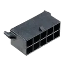
| Description | Mega-Fit vertical header, through-hole, shrouded, 4-wall, male pin header |
| Positions | 10 circuits |
| Rows | 2 rows, 5 positions per row |
| Pitch | 5.70 mm |
| Row spacing | 5.70 mm |
| Mount / termination | Through-hole solder |
| Plating | Tin (Sn) contact plating, nickel underplating |
| Housing material | LCP, UL94 V-0 / glow-wire capable |
| Color | Black |
| Voltage rating | 600 V max per product/family data |
| Current rating | Family maximum around 23 A per contact; fully-loaded 10-circuit current depends on wire size, e.g. approximately 10–14 A for 16–12 AWG per product spec table |
| Operating temperature | -40 °C to +105 °C for tin version |
| Durability | 25 mating cycles for tin version |
| Recommended PCB contact hole | Ø1.80 ±0.05 mm |
| Recommended locator/peg hole | Ø3.00 ±0.05 mm |
| Recommended PCB thickness | 1.58–2.36 mm |
| 10-circuit drawing dimensions | DIM A 29.15 mm, DIM B 36.19 mm, DIM C 33.14 mm basic, DIM D 37.20 mm |
Schematic symbol cross-check
Observed symbol terminals:
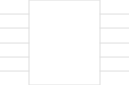
- 10 terminal components, pin numbers 1 through 10.
- All terminal pin types are Passive.
- Symbol is arranged as two opposing columns:
- Pins 1–5 on the left.
- Pins 6–10 on the right.
- Pin number property exists for every terminal.
- No electrical nets are present, which is normal for a reusable connector part definition.
Assessment:
- Pin count matches the datasheet/drawing: PASS.
- Pin numbering coverage 1–10 is complete: PASS.
- Passive pin type is appropriate for connector contacts: PASS.
- Symbol organization as two 5-pin rows is consistent with the 2×5 connector: PASS.
- Pin descriptions are minimal/absent beyond pin number and type; for a simple connector this is acceptable, but adding explicit descriptions such as
Contact 1...Contact 10would improve clarity: MINOR IMPROVEMENT.
Footprint cross-check
Observed footprint asset:
768290010.kicad_mod.Observed copper pads:
Table
| Pad | Observed location in footprint asset | Datasheet expectation |
|---|---|---|
| 1 | (0.000, 0.000) mm | 2×5 5.70 mm grid |
| 2 | (-5.700, 0.000) mm | 5.70 mm pitch |
| 3 | (-11.400, 0.000) mm | 5.70 mm pitch |
| 4 | (-17.100, 0.000) mm | 5.70 mm pitch |
| 5 | (-22.800, 0.000) mm | 5.70 mm pitch |
| 6 | (0.000, -5.700) mm | 5.70 mm row spacing |
| 7 | (-5.700, -5.700) mm | 5.70 mm row spacing |
| 8 | (-11.400, -5.700) mm | 5.70 mm row spacing |
| 9 | (-17.100, -5.700) mm | 5.70 mm row spacing |
| 10 | (-22.800, -5.700) mm | 5.70 mm row spacing |
Observed hole/pad sizes:
- Contact pads: through-hole circular, pad diameter 2.775 mm, drill 1.85 mm.
- Mounting/locator holes: NPTH circular, size/drill 3.05 mm.
- Mounting holes at approximately (-27.970, -6.025) mm and (5.170, -6.025) mm in the KiCad footprint asset.
Assessment:
- Contact pad count matches 10 positions: PASS.
- 2×5 grid, 5.70 mm pitch and row spacing match datasheet: PASS.
- Contact drill is 1.85 mm vs drawing Ø1.80 ±0.05 mm; 1.85 mm is at the upper tolerance limit: ACCEPTABLE / VERIFY FAB PREFERENCE.
- Locator drill is 3.05 mm vs drawing Ø3.00 ±0.05 mm; 3.05 mm is at the upper tolerance limit: ACCEPTABLE / VERIFY FAB PREFERENCE.
- Footprint includes two locator holes: PASS.
- Silkscreen/fab outline appears consistent with a large shrouded vertical connector body: PASS.
Project property review
Observed project properties:
- Datasheet URL: set.
- Mount:
Wire. - Manufacturer Name:
Molex. - Designator Prefix:
J. - Part Type:
Connectors. - Manufacturer Part Number:
0768290010. - Symbol Style:
parametric-v1.
Assessment:
- MPN and manufacturer match official part: PASS.
- Designator prefix
Jis appropriate for connector/header: PASS. - Part Type
Connectorsis appropriate: PASS. - Mount property
Wireis questionable for this part because the PCB side is through-hole solder; the mating side is wire-to-board. If this property is intended to describe PCB mounting, it should beThrough Hole. If it is intended as connector application,Wire-to-Boardis acceptable elsewhere as a connector type/property: MISMATCH / AMBIGUOUS. - Package/property information is not explicitly set as
2x5 through-hole vertical header, 5.70 mm pitch; adding this would improve searchability: MINOR IMPROVEMENT.
Automated review checks
Component review checks queried:
- MPN
- Manufacturer
- Datasheet
- Terminal
- Terminal pin number
- Terminal parametric
- Missing properties
Result: no matching ERROR, WARNING, UNCERTAIN, or OPEN checks were reported.
Mismatches / recommended fixes
-
Mount property may be wrong/ambiguous
- Current:
Wire - Recommended if it means PCB mount:
Through Hole - Reason: 0768290010 is a through-hole PCB header; it mates to a wire harness but is not wire-mounted.
- Current:
-
Datasheet URL is set to an uploaded storage PDF, not the official Molex URL
- This is not a functional mismatch because a datasheet exists.
- If strict official-link provenance is desired, update it to the exact Molex customer drawing URL or store both family datasheet and drawing as reference URLs.
-
Pin descriptions are minimal
- Current terminals have pin numbers and passive type but no descriptive text.
- Recommended descriptions:
Contact 1throughContact 10, orMega-Fit power contact 1throughMega-Fit power contact 10.
-
Contact and locator drill sizes are at the upper datasheet tolerance limit
- Contact drill: 1.85 mm vs 1.80 ±0.05 mm.
- Locator drill: 3.05 mm vs 3.00 ±0.05 mm.
- This is likely acceptable, but should be verified against the intended PCB manufacturer’s finished-hole tolerance.
Overall conclusion
The part is substantially consistent with the official Molex 0768290010 / 76829-0010 documentation. The symbol has the correct 10 passive terminals and complete pin numbering, and the footprint implements the expected 2×5 5.70 mm through-hole layout with locator holes. The only notable issue is the ambiguous
Mount: Wire property; if this property describes PCB mounting, it should be changed to Through Hole.Reviewed source data
Key datasheet / drawing specs
Schematic symbol cross-check
Footprint cross-check
Project property review
Automated review checks
Mismatches / recommended fixes
Overall conclusion