Part Datasheet Review and Validation
Thought for 1 min 50 sec
Here’s a complete, step-by-step execution for your part project.
- Review of available part information (from the project)
- MPN: 5103308-6
- Manufacturer: TE Connectivity
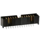
- Part name/series (from description): Low profile, daisy-chain capable, dual-row PCB connector
- Number of positions: 26
- Number of rows: 2
- Orientation: Vertical
- Contact current rating (max) in project description: 1 A
- Mating post: 0.025 in (0.64 mm) square
- Mount: PCB
- Designator prefix: J
- Project property “Part Type”: Integrated Circuits (mismatch; should be Connector)
- Datasheet URL present in project: https://www.te.com/commerce/DocumentDelivery/DDEController?Action=srchrtrv&DocNm=82012_Ribbon_Cable_Interconnect_Sol&DocType=Catalog%20Section&DocLang=English&PartCntxt=5103308-6&DocFormat=pdf
- Datasheet URL check and update
- A datasheet URL is already set on the part. No change made.
- Datasheet scan and metadata extraction (TE “Ribbon Cable Interconnect Solutions” for 5103308-6)
Electrical ratings
- Rated voltage: 300 V
- Dielectric withstanding voltage: 1000 V rms (at sea level)
- Current rating: 1.5 A max; also listed as 0.5 A per contact at thermal rise conditions in catalog notes (context-dependent)
- Insulation resistance: 5000 MΩ minimum (initial)
- Contact resistance: value shown in catalog section is 10 mΩ max (catalog OCR sometimes renders “mΩ” as “MΩ”; the intended unit is milliohms for contact resistance)
Mechanical and package
- Series/Type: Low Profile Pin Headers, Center and Dual Polarized, 0.100 in x 0.100 in [2.54 mm x 2.54 mm] centerlines
- Positions: 26
- Rows: 2
- Pin/post: 0.025 in [0.64 mm] square (mating end)
- Orientation: Vertical PCB mount
- Body dimensions (for the 26-position variant):
- A: 1.600 in [40.64 mm]
- B: 1.200 in [30.48 mm]
- Additional dimensional callouts around the header and leads include typicals such as 0.100 in [2.54 mm] pitch, 0.360 in [9.14 mm], 0.130 in [3.30 mm], 0.388 in [9.86 mm], 0.185 ± 0.010 in [4.70 ± 0.25 mm], 0.120 ± 0.015 in [3.05 ± 0.38 mm], 0.240 in [6.10 mm] typ.
Recommended PCB layout (manual insertion)
- Grid pitch: 0.100 in [2.54 mm] typ. in both directions
- Drill hole diameter: 0.035 ± 0.003 in [0.89 ± 0.08 mm] typ.
- Post size tolerance: 0.025 ± 0.001 in [0.64 ± 0.03 mm]
- Overall length reference: A = 1.600 in [40.64 mm]; width reference: B = 1.200 in [30.48 mm]
Pin description and numbering
- Dual-row numbering with clear Pin 1 indicator; Pin 1 and Pin 2 are called out in drawings for the series. The catalog shows position #1 indicator and typical odd/even opposing sides for 2-row headers.
Materials and plating
- Housing: Glass-filled nylon, UL 94V-0, black
- Posts: Brass
- Plating (B option for this part number):
- Mating surfaces: Gold flash over palladium-nickel, 0.000015 in [0.00038 mm] minimum total
- Solder area: Tin, 0.000100 in [0.00254 mm] minimum
- Underplate: Nickel, 0.000050 in [0.00127 mm] minimum (entire post)
Special features and mating
- Polarization: Center and dual polarized features identified in series description and drawings (position #1 indicator present)
- Mating families called out in the catalog: AMPMODU wire-applied/board-mount receptacles and related families; for 26 positions in this header series the paired numbers include 5103309-6 (related vertical mount family) and 5103308-6 on the “Plating B” column for this low-profile header
Compliance
- RoHS compliant (per catalog statement)
- UL flammability for the housing: UL 94V-0 (catalog references UL file for series; verify exact file if needed on TE’s website for this MPN)
- Cross-check: schematic symbol and footprint vs datasheet
Symbol
- Pin count: 26 present in the symbol editor assets. Matches datasheet.
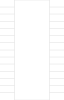
- Arrangement: Dual-row representation observed (pins placed on left/right columns). Matches the 2-row header concept.
- Numbering convention: The datasheet clearly indicates a Pin 1 indicator with opposing Pin 2 and dual-row layout. The symbol appears to organize pins on left/right columns (odd/even) consistent with typical TE numbering; ensure the Pin 1 marker in the symbol matches the physical end indicated in the datasheet drawing. Risk if mirrored: net assignment reversal across the rows.
Footprint
- Pad count: 26 pads present in the footprint asset index. Matches datasheet.
- Mounting style: Datasheet specifies through-hole with 0.035 ± 0.003 in [0.89 ± 0.08 mm] drill. Verify the pad hole size and annular ring in your footprint match these values. The current layout index lists 26 pads but does not expose pad drill/land dimensions in the data retrieved; please confirm hole size, annular ring, and 2.54 mm grid in the footprint editor.
- Pitch and grid: Datasheet requires 2.54 mm x 2.54 mm grid. Confirm your pads are placed on an exact 2.54 mm grid for both X and Y, and that the overall A and B spacings match the 26-position callouts (A=40.64 mm, B=30.48 mm).
- Pin 1 indicator: Ensure a clear silkscreen or assembly layer marker aligns with the datasheet Pin 1 location so assembly and mating orientation are unambiguous.
Project properties and sourcing checks
- Part Type mismatch: The project property shows “Integrated Circuits” but this MPN is a dual-row through-hole connector. Recommend updating the part’s type to Connector to avoid misclassification in BOMs and sourcing tools.
- Current rating inconsistency: The project description lists 1 A max per contact; the datasheet indicates 1.5 A max (with separate thermal-rise test context noted). If your system derating requires 1 A, keep it; otherwise align the stated rating with datasheet and document any derating choice.
- Through-hole confirmation: Ensure the part asset and footprint are designated as through-hole and not SMD; datasheet recommends drilled holes per above.
Suggested next corrections
- Update the part “Part Type” to Connector.
- Verify and, if needed, adjust pad drill to 0.89 mm and place pads on a 2.54 mm grid consistent with A/B dimensions.
- Add/verify a Pin 1 silkscreen/assembly marker to match datasheet.
- Align the documented current rating with the datasheet (1.5 A max) or maintain a documented derating rationale.
Reference component link
- Consider using or mapping to 5103308-6 when placing in a design.
@layout drill details
@help edit part properties
@review manufacturing checks
@library find matching part
Pin 1 marker check