Part Datasheet Review and Validation
Review all available part information (MPN, package, pin count, description, properties). If no datasheet URL is already set, search the web for the official datasheet and update the part's Datasheet property with the URL. Then cross-check the schematic symbol, footprint, and pin descriptions against the datasheet. Summarize key specs and flag any mismatches.
Worked for 4 mins 36 sec
I reviewed the part against the official Amphenol documentation and set the Datasheet URL to the official Amphenol USB 3.2 Type-C datasheet. Main flags: the four GND contacts are typed as
Power In instead of Ground, the project has 10 shield terminals while the official drawing lists 4 shield pads, and several metadata/pin-description fields are missing; full details are in Part Review: Amphenol 124018402112A. I followed the part-project datasheet-sync requirement to use the datasheet/drawing as the source of truth for exact pin count and pin numbering .Fix pin mismatches
Clean metadata
Compare pad mapping
Run ERC/DRC
Set Datasheet URL to "https://cdn.amphenol-cs.com/m..."
0:03
Set Datasheet URL to "https://cdn.amphenol-cs.com/media/wysiwyg/files/documentation/datasheet/inputoutput/io_usb_3_2_type_c.pdf"
Created project doc "Part Review: Amphenol 124018402112A"
Refine this doc
Ask about this doc
Part Review: Amphenol 124018402112A
Scope
Reviewed current part-project information, schematic terminal elements, PCB footprint pads/assets, official Amphenol documentation, and extracted datasheet/drawing data. The review follows the part-project datasheet-sync rule that pin count and pin numbers must be taken from the datasheet/drawing as the source of truth, including shell/shield contacts where listed.
Official documentation used
- Product page: https://www.amphenol-cs.com/product/124018402112a.html
- Official eBrochure / datasheet: https://cdn.amphenol-cs.com/media/wysiwyg/files/documentation/datasheet/inputoutput/io_usb_3_2_type_c.pdf
- Official drawing: https://cdn.amphenol-cs.com/media/wysiwyg/files/drawing/124018402112a.pdf
- Product specification: https://cdn.amphenol-cs.com/media/wysiwyg/files/documentation/ps-susb013.pdf
Project data reviewed
Existing project metadata
- Project name:
124018402112A - Manufacturer Part Number:
124018402112A - Designator Prefix:
J - Existing description: includes
A,Manufacturer Recommendation,KARTHIK,3.19 mm,Amphenol ICC (Commercial Products) - Datasheet URL: was not shown as a normal project property in the visible project context at the start; it has now been set to the official Amphenol USB 3.2 Type C datasheet URL.
Assets
- Symbol SVG:
124018402112A 124018402112A_0_0 Symbol.svg - Footprint:
AMPHENOL_124018402112A.kicad_mod - 3D model:
124018402112A.STEP
Schematic symbol / terminals found
- 34 terminal elements total.
- 24 USB Type-C signal/power/ground contacts: A1-A12 and B1-B12.
- 10 shield terminals with pin numbers
SH1_1,SH1_2,SH1_3,SH1_4,SH2_1,SH2_2,SH2_3,SH2_4,SH3,SH4.
PCB footprint pads found
- 34 pad nodes corresponding to the 34 schematic terminals.
- Footprint asset is present and labeled for this MPN.
Official part identity and key specs
From Amphenol documentation:
- Manufacturer: Amphenol Communications Solutions / Amphenol ICC
- MPN:
124018402112A - Family: USB 3.2 Type-C
- Product status: Active, per product page
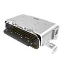
- Description: USB 3.2 Gen 2, Type C, receptacle, right angle, mid-mount, center height 1.10 mm, dual-row SMT
- Contact count: 24 signal/power contacts
- Shield pads in official drawing: 4 shield pads, S1-S4
- Data rate: USB 3.2 Gen 2, 10 Gb/s; family datasheet also describes USB 3.2 Type-C solutions up to 20 Gb/s for other variants
- Mounting / termination: mid-mount, right-angle, dual-row surface mount
- Center height: 1.10 mm
- Packaging: Tape and reel; drawing notes 1000 pcs/reel, 8 reels/carton
- Operating temperature: -40 °C to +85 °C
- Durability: 10,000 cycles
- Contact resistance: 40 mΩ max
- Insulation resistance: datasheet says 100 MΩ min; drawing says 1000 MΩ min
- Withstanding voltage: datasheet says 100 VAC; drawing says 500 VAC/minute
- Current rating: product/datasheet summary says 5 A max/up to USB PD; drawing gives per-pin limits: 6.0 A for VBUS and GND pins, 1.0 A for SBU1/SBU2, 0.25 A for other pins
- Voltage rating: product page/spec/drawing differ; drawing note says 5 VAC, product spec reportedly states 20 V max, product page lists 100 V. This should be treated as a documentation inconsistency for any power-rating-critical design.
Official pin/contact assignment from drawing
Table
| Contact | Official name | Project terminal found | Project Pin Type | Review |
|---|---|---|---|---|
| A1 | GND | GND_A | Power In | Mismatch: should be Ground |
| A2 | TX1+ | TX1+ | Bi-Directional | OK |
| A3 | TX1- | TX1- | Bi-Directional | OK |
| A4 | VBUS | VBUS_A | Power In | OK |
| A5 | CC1 | CC1 | Bi-Directional | OK |
| A6 | D+ | D1+ | Bi-Directional | Acceptable unique label, but differs from drawing name D+ |
| A7 | D- | D1- | Bi-Directional | Acceptable unique label, but differs from drawing name D- |
| A8 | SBU1 | SBU1 | Bi-Directional | OK |
| A9 | VBUS | VBUS_A__1 | Power In | OK |
| A10 | RX2- | RX2- | Bi-Directional | OK |
| A11 | RX2+ | RX2+ | Bi-Directional | OK |
| A12 | GND | GND_A__1 | Power In | Mismatch: should be Ground |
| B1 | GND | GND_B | Power In | Mismatch: should be Ground |
| B2 | TX2+ | TX2+ | Bi-Directional | OK |
| B3 | TX2- | TX2- | Bi-Directional | OK |
| B4 | VBUS | VBUS_B | Power In | OK |
| B5 | CC2 | CC2 | Bi-Directional | OK |
| B6 | D+ | D2+ | Bi-Directional | Acceptable unique label, but differs from drawing name D+ |
| B7 | D- | D2- | Bi-Directional | Acceptable unique label, but differs from drawing name D- |
| B8 | SBU2 | SBU2 | Bi-Directional | OK |
| B9 | VBUS | VBUS_B__1 | Power In | OK |
| B10 | RX1- | RX1- | Bi-Directional | OK |
| B11 | RX1+ | RX1+ | Bi-Directional | OK |
| B12 | GND | GND_B__1 | Power In | Mismatch: should be Ground |
Shield / shell comparison
Official drawing lists 4 shield pads: S1, S2, S3, S4.
Project has 10 shield terminals:
SHIELD=SH1_1SHIELD__1=SH1_2SHIELD__2=SH1_3SHIELD__3=SH1_4SHIELD__4=SH2_1SHIELD__5=SH2_2SHIELD__6=SH2_3SHIELD__7=SH2_4SHIELD__8=SH3SHIELD__9=SH4
Review: this is the largest mismatch. The official drawing exposes 4 shield pad identifiers, while the current part has 10 shield terminal/pad entries. This may reflect internal/mechanical sub-pads in the imported footprint, but it does not match the drawing's logical shield pad numbering. If this part is intended for schematic use, consider consolidating or renaming shield terminals to S1-S4 after verifying the footprint pad geometry.
Footprint cross-check
- Footprint asset exists and pad nodes align with all schematic terminals.
- Project footprint pad count: 34.
- Official drawing recommended footprint pad count: 28 total = 24 contacts + 4 shield pads.
- Mismatch: footprint/schematic represent 10 shield pads rather than 4 shield pads.
- Because the footprint came from a KiCad asset for this exact MPN, the extra shield pads may be deliberate split metal tabs; however, the logical pin numbering does not match the official drawing and should be manually verified against the imported KiCad footprint geometry and Amphenol drawing.
Property/metadata gaps
Recommended additions or corrections:
Manufacturer Name: Amphenol Communications Solutions / Amphenol ICCPart Type: ConnectorConnector Type: USB Type-C ReceptaclePackage or Case Code: Right-angle mid-mount dual-row SMT, center height 1.10 mmConnector Gender: ReceptacleConnector Positions: 24 contacts + shieldMount: SMT / mid-mountOperating Temperature: -40 °C to +85 °CMax Current: For VBUS/GND, drawing states 6.0 A; family datasheet states 5 A max/up to USB PD. Use caution.Voltage Rating: Do not set automatically due to documentation inconsistency between product page/spec/drawing.
Mismatches and flags
- GND pin type mismatch: A1, A12, B1, and B12 are set as
Power In; they should beGround. - Shield pad count/numbering mismatch: datasheet drawing lists 4 shield pads S1-S4; project has 10 shield terminals/pads named SH1_1 through SH4.
- Pin descriptions are missing: terminals have Pin Type and Pin Number, but no
Pin Descriptionproperty was present in the schematic data. - Project metadata is incomplete: manufacturer name, part type, connector type/gender, package/case code, operating temperature, and mount are not present as standard part metadata in the visible project properties.
- Description is not library-ready: the description does not clearly state the part function and key specs. Suggested description:
USB 3.2 Gen 2 Type-C receptacle, right-angle mid-mount, 1.10 mm center height, dual-row SMT. - Electrical ratings conflict across Amphenol documents: current and voltage ratings vary between the product page, product specification, drawing, and family datasheet. Use the official drawing/spec and confirm with Amphenol for critical USB-PD applications.
Suggested next fixes
- Change A1/A12/B1/B12 Pin Type to
Ground. - Add concise pin descriptions to all USB contacts.
- Decide whether shield terminals should remain as 10 footprint-level shell pads or be simplified/renamed to S1-S4 for the part symbol.
- Add missing metadata properties listed above.
- Update the project description to the suggested functional description.


Welcome 👋
Flux accelerates your PCB design with AI.
Create your account to start using this component and bring your ideas to life.