Chat

Welcome to Flux

Treat Flux like your intern. Tell it what you'd like to build and it'll get to work. You can also ask it questions, brainstorm ideas, and teach it your preferences. Learn More

Explain project
Write a project description
Find schematic issues
Create a test plan
Simulate a circuit
Prepare for Manufacturing
Component Selection Workflow
New Subsystem Wizard
Check that none of the unconnected pins require pull-up or pull-down resistors t...

@copilot Check that none of the unconnected pins require pull-up or pull-down resistors to ensure proper function.
2y
Given the components listed in your project, you have two Hirose Electric DF40C-100DS-0.4V51 connectors (designated as J1 and J2) and a Silvertel AG9712-2BR module. To determine the need for pull-up or pull-down resistors on unconnected pins, we need to consider the typical usage and datasheets of these components.
For Hirose Electric DF40C-100DS-0.4V51 Connectors (J1 and J2)
These are connectors, and the need for pull-up or pull-down resistors on their pins depends on what they connect to. Generally, for connector pins directly interfacing with microcontrollers (MCUs) or other integrated circuits (ICs), it's the connected IC's datasheet (in this case, possibly a compute module like Raspberry Pi CM4's GPIOs) that specifies whether certain lines require pull-up or pull-down resistors. Such resistors are often used for I2C bus lines (SDA/SCL with pull-ups), GPIOs configured for certain functionalities, or to ensure a defined state on unused pins.
For Silvertel AG9712-2BR Module
  • VA1, VA2, VB1, and VB2: These pins are typically associated with the VoIP analog output interface. In most applications, they won't require pull-up or pull-down resistors but should be appropriately filtered and connected according to the module's application circuits.
  • IC_1 and IC_2: These pins are internally connected and often don't require any external resistors. They are typically used for factory testing or specific configurations based on the datasheet or application notes.
  • NC (No Connection): This pin should not be connected and thus does not require any resistor.
  • -VDC and +VDC: These are power supply pins and will not need pull-up or pull-down resistors. Ensure they are connected to the appropriate power source as specified in the datasheet.
  • ADJ: Depending on the specific use case (e.g., output voltage adjustment), this pin might be left unconnected or connected through a resistor to ground or VDC. Check the datasheet for any specific guidance.
Recommendations:
  • Cross-reference the datasheets: For all ICs and modules you are interfacing with (especially for the CM4 module connected to the DF40C-100DS-0.4V51 connectors), carefully check their datasheets or application notes for any specific instructions on pull-up or pull-down resistors.
  • Default assumption for GPIOs: If specific guidance is not available and you have unconnected GPIO pins, a common practice is to add 10kΩ pull-up or pull-down resistors to keep them in a known state and prevent floating inputs, but this depends on the intended circuit's behavior.
Please check the datasheets or application notes for the specific components you're interfacing with (Raspberry Pi CM4 for J1 and J2, and the specific application circuit for AG9712-2BR) for definitive guidance. Without exact details on the connections and external circuitry, the recommendations above are based on common practices and may need adjustments to fit your exact requirements.
2y
1

No files yet

Documents

    Documents are markdown text files which describe project goals, capture details, or even simulation outputs.

    Assets

    tesdf.png

    tesdf.png

    tesdfThumbnail
    stp

    CM4-step.stp

    CM4-step3D Model

    CM4 Template

    CM4 Template thumbnail
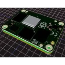
    This is a template for easy and fast developing HAT for RPI CM4! #RPI #CM4 #Template

    Pricing & Availability

    Distributor

    Qty 1

    Controls