Chat
Welcome to Flux
Treat Flux like your intern. Tell it what you'd like to build and it'll get to work. You can also ask it questions, brainstorm ideas, and teach it your preferences. Learn More
Help me brainstorm ideas
Design a block diagram
Find parts in the library
Read a datasheet
Simulate a circuit
New Subsystem Wizard
create a high level mermaid block diagram of L1. Include key component's manufac...

2y
For your Raspberry Pi 4 Hat project, selecting the appropriate inductor is crucial for various applications such as filtering, power supply, or RF circuits. The choice depends on the application's requirements like the desired inductance value, current handling capability, and size constraints. Given the information in your project, it seems like the inductor would likely be used in power management or filtering roles associated with the Raspberry Pi and peripherals' power supply.
Considering a typical power management application in your project, here are a few inductor choices from Bourns, based on different inductance values and their characteristics. Please cross-reference these suggestions with your specific requirements, such as maximum current (I rms) and saturation current (I sat), to ensure compatibility:
-
For Moderate Inductance and High Current Applications:
- Bourns Part No.: SRR1210-270M
- Inductance: 27 µH
- I rms (A): 5.0
- I sat (A): 4.2
- Bourns Part No.: SRR1210-270M
-
For High Inductance and Moderate Current Applications:
- Bourns Part No.: SRR1210-680M
- Inductance: 68 µH
- I rms (A): 3.0
- I sat (A): 2.7
- Bourns Part No.: SRR1210-680M
-
For Low Inductance and Very High Current Applications:
- Bourns Part No.: SRR1210-1R8Y
- Inductance: 1.8 µH
- I rms (A): 10.2
- I sat (A): 13.2
- Bourns Part No.: SRR1210-1R8Y
-
For High Inductance and Low Current Applications:
- Bourns Part No.: SRR1210-820M
- Inductance: 82 µH
- I rms (A): 2.8
- I sat (A): 2.5
- Bourns Part No.: SRR1210-820M
Each of these inductors has its unique application based on the current requirements and inductance needed for your project. Ensure the chosen inductor fits into your design's physical space and meets any other specific requirements like the Quality factor (Q) or Self-Resonant Frequency (SRF) that might be critical for your application.
2y
2y
Certainly! Based on the project description you've provided, let's create a high-level Mermaid block diagram focusing on the inductor L1, its immediate connections, and including manufacturer part numbers (MPN) wherever possible.
For L1, we're noting its connection within the switching network of the voltage regulator circuit, specifically connected to the U1 (LM2678SD-5.0/NOPB) switching regulator and integral in forming the output stage with D1 (PDS760-13) and capacitors C1, C4, C5, and C6. The MPN for L1 isn't provided, so it will be marked as unspecified in the diagram.
Here is a text-based representation of the Mermaid diagram:
graph TD;
    L1["L1 (Inductor)"] --- |"P1"| FatPath["abb6c0094b0f5d45c059501b1638c974"];
    L1 --- |"P2"| L1_to_U1_FB["2e79598adb9cc0973589b99d9a0262d4"]

    subgraph abb6c0094b0f5d45c059501b1638c974[""Net: abb6c0094b0f5d45c059501b1638c974""];
        C1["C1 (0.01u)"] --> D1["D1 (PDS760-13)"];
        U1_SW["U1:SW (LM2678SD-5.0/NOPB)"] --> L1;
        L1 --> U1_SW;
    end

    subgraph node_2e79598adb9cc0973589b99d9a0262d4[""Net: node_2e79598adb9cc0973589b99d9a0262d4""];
        L1_to_U1_FB --> U1_FB["U1:FB (LM2678SD-5.0/NOPB)"];
        L1_to_U1_FB --> C2["C2 (100u)"];
        L1_to_U1_FB --> J1_VBUS["J1:VBUS"];
        L1_to_U1_FB --> J2_VBUS["J2:VBUS"];
    end

    U1_SW --> SW_to_D1["9cb2b1d3207df54b01c1f6e4302a6654"];

    subgraph node_9cb2b1d3207df54b01c1f6e4302a6654[""Net: node_9cb2b1d3207df54b01c1f6e4302a6654""];
        D1 --> |"A1, A2"| SW_to_D1;
        SW_to_D1 --> |"Connection to load and feedback network"| Load["To Load and Feedback Network"];
    end
Note: In this Mermaid syntax:
- The blocks represent components and their respective MPNs when available or specified.
- The connecting lines (
---and-->) represent electrical connections between components, with the line labels indicating the pin or the net number associated with that connection. - Due to the limitations of text representation, the precise layout of nets and their connections are simplified. The diagram illustrates L1's pivotal role in the buck converter configuration surrounding U1, C2's interaction with the 5V supply, and D1's connection to the switching node managed by U1.
- "P1" and "P2" next to edges represent the connection points to and from L1 in the respective nets.
This abstracted view centers on L1 and its critical relationships with other components in the buck converter circuit. It doesn't encapsulate every detail of the circuit but highlights the most relevant connections based on your request.
2y
Someone is typing...
7
No files yet
Reviews

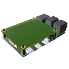
Template for Raspberry Pi 4 Shield. Include an official pinout so you will always know Raspberry Pi names, the alternative roles of pins, which one is SDA, or SCL, etc. On PCB you can find the 3D model of the Raspberry Pi itself along with the board outline on the silkscreen.
#RaspberryPi #Raspberry #Pi #RPi #Shield #template #project #project-template #raspberry
Pricing & Availability
Distributor | Qty 1 |
|---|
Controls
Welcome 👋
Flux helps you build PCBs faster with an AI teammate!
Create your account to collaborate, stay updated, fork your own version, and get instant answers from our AI agent.
yoitsjigs
copilot