Treat Flux like your intern. Tell it what you'd like to build and it'll get to work. You can also ask it questions, brainstorm ideas, and teach it your preferences. Learn More
Writing code for an Arduino Uno simulation involves writing a script in C/C++ based on the Arduino framework. This code is then uploaded to the Arduino Uno through the Arduino IDE. However, the exact code depends on the specific requirements of your circuit and what the simulation model needs to achieve.
Based on your circuit and without specific requirements, I'll draft a simple example to blink an LED which is one of the most basic Arduino sketches.
C
// the setup function runs once when you press reset or power the boardvoidsetup(){// Initialize digital pin LED_BUILTIN as an output.pinMode(LED_BUILTIN, OUTPUT);}// The loop function runs over and over again forevervoidloop(){digitalWrite(LED_BUILTIN, HIGH);// Turn the LED on (HIGH is the voltage level)delay(1000);// Wait for one seconddigitalWrite(LED_BUILTIN, LOW);// Turn the LED off by making the voltage LOWdelay(1000);// Wait for one second}
This basic code sets up one of the onboard LEDs and then sets it to alternately turn on and off every second. If you could please provide what specific tasks you want to simulate, I'd be happy to create a more specific Arduino code for your use.
Once you have the code, you can simulate your Arduino code using various simulation tools such as Proteus or online simulators like Tinkercad or circuits.io. You simply need to upload your Arduino code to the simulator and run the simulation.
Please let me know what functionalities of the components you're using in the schematic that you want to simulate in the Arduino Uno.
Without specifics about the exact use-case of J2 in your schematic, it can be challenging to recommend a precise replacement. However, considering that J2 is a common connector, with 8 pins, I can suggest a general replacement.
One reasonable guess is that J2 is being used as a header connector for interfacing with other boards or modules. In this case, I will recommend the "Pin Header, Straight, Single Row, 8 Pins" as a replacement. It's a common connector with 8 pins often used for general purposes.
Please check if the specific electrical characteristics (current rating, voltage rating), mechanical constraints (pitch, orientation), and mounting style (thru-hole, surface-mount) of this connector meet your needs in the context of your design. Also ensure the pin arrangement and numbering align well with your project requirement.
But let me remind you that it's always a good idea to double-check your exact requirements to ensure any replacement part fully meets your needs.
2y
3
No files yet
Reviews
Documents
Documents are markdown text files which describe project goals, capture details, or even simulation outputs.
Assets
step
Arduino UNO.STEP
Arduino UNO 3D3D Model
dxf
Arduino UNO R3 shield - Shape.dxf
Arduino UNO R3 shield - Shape
Arduino Uno R3 Shield Template-removebg-preview.png
Arduino Uno R3 Shield Template-removebg-previewThumbnail
young boy doing things
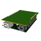
Template for Arduino Uno R3 Shield. Include an official pinout so you will always know Arduino names, the alternative roles of pins, which one is SDA, or SCL, etc. On PCB you can find the 3D model of the Arduino Uno R3 itself along with the board outline on the silkscreen.
#Arduino#Uno#Shield#Template#project-template #project
Properties
Properties describe core aspects of the project.
Pricing & Availability
Distributor
Qty 1
LCSC
$57.17
Mouser
$37.50
Controls
Welcome ๐
Flux helps you build PCBs faster with an AI teammate!
Create your account to collaborate, stay updated, fork your own version, and get instant answers from our AI agent.
votie
copilot