ESP32C3 XIAO Circuit Connections
Thought for 30 sec
Below are the steps documented for adding custom board dimensions and M3 mounting holes:
- In the PCB editor, set the board outline to 3 cm in length and 2 cm in breadth.
- Next, search the library for the M3 Mounting Hole component.
- Place these mounting holes at the desired board locations (typically, one at each corner of the board) and adjust their positions as needed.
For more detailed, step-by-step guidance on setting board dimensions and adding mounting holes, please refer to the official Flux documentation here: Flux Documentation.

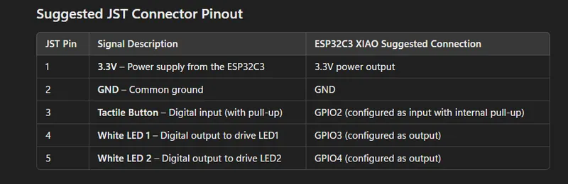
Image
Thought for 28 sec
It appears the image shows a pinout table for a 5-pin JST connector, indicating each pin’s function (3.3V, GND, Tactile Button, White LED 1, and White LED 2) and how they map to an ESP32C3 XIAO board’s GPIO pins. Let me know if you’d like any of this pin information incorporated into your schematic or PCB design in Flux.
Thought for 47 sec
help { "query":"incorporate ESP32C3 XIAO pinout into my schematic" }
Add ESP32C3 XIAO to schematic
Pinout validation
Check for conflicts


vivek17
copilot
-
LED1 and LED2:
- Make sure they are connected with the correct polarity. The anode (A) should connect towards the positive side and the cathode (K) towards the negative side.
-
Tactile Button:
- Check if the tactile button connections align with the intended function. It seems the button connects
-
Resistors R1 and R2:
- R1 is connected between
- R2 is connected between
- Double-check if these are the intended locations for limiting the current through the LEDs.
JST ConnectorTACTILE BUTTON:3toJST:1throughNet 5, andTACTILE BUTTON:1toJST:2throughNet 6.JST:5andLED1:A.JST:4andLED2:A.- The
- Pin 1 Net5 connects to LED1 and LED2 cathodes and the tactile button's pin 3.
- Pin 2 Net6 connects to one side of the tactile button.
- Pin 4 Net3 connects to one side of R2.
- Pin 5 Net1 connects to one side of R1.
RecommendationsJSTconnector has pins connecting to various components. Ensure that these connections: