Boost Converter Project Overview
1:46
Below is an overview of the TPS61032RSAR Module project based on the available project data and schematic details:
Project Purpose
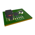
This project implements a boost (step-up) converter module that is based on the TPS61032RSAR from Texas Instruments. Designed as a submodule for power management, the circuit aims for a 96% efficiency while supporting up to 4 A in a switch-mode configuration. The module is intended for applications where an input voltage must be converted to a higher, regulated output voltage with high efficiency.
Core Components
| Component | Role | Reference |
|---|---|---|
| TPS61032RSAR (IC1) | Main boost converter IC performing the switching operation and voltage conversion | TPS61032RSAR |
| Passive Resistors (R1, R2, R3, R4, R5) | Form part of the feedback network and other biasing/protection networks. They help set the converter’s output voltage. | R1, R2, etc. |
| Passive Capacitors (C1, C2, C3) | Provide decoupling, filtering, and voltage smoothing. One capacitor is used as bulk capacitance while another provides high-frequency noise filtering. | C1, C2, C3 |
| Inductor (L1) | Serves as the energy storage element during the switching operation; its value is critical for ensuring proper energy transfer. | L1 |
| Terminals and Net Portals | VIN and VOUT terminals establish the connection for input and output power, while ground GND components ensure a common return path. | Various terminal symbols as defined in the schematic |
| Route Branch Points and Net Portals (FB, LBI, etc.) | Facilitate proper net labeling and connectivity across the schematic, ensuring that critical signals (like the feedback loop) are routed correctly. | FB, LBI |
How the Components Interact
-
Power Conversion
- The TPS61032RSAR is the heart of the design. It regulates the boost conversion process by switching current through the inductor (L1).
- During the switching cycle, energy is stored in L1 when the switch is closed and then released to the output when the switch opens.
-
Feedback & Regulation
-
Decoupling and Filtering
-
Connectivity and Signal Integrity
Design and Implementation Breakdown
-
Schematic Layout:
The schematic is drawn in Flux, where each component is placed with its connections clearly defined. Critical nets such as feedback, switching nodes, and power rails are highlighted using net portals and branch points to maintain connectivity throughout the design. -
Component Selection:
Values for passive components (capacitors for decoupling/filtering, resistors for setting the output voltage via the feedback network, and an inductor for energy storage) have been chosen by referring to standard industry practices and datasheet recommendations from Texas Instruments. The selection aims to balance efficiency, size, and performance. -
Signal Flow:
The TPS61032RSAR regulates the boost conversion:- Input Stage: Power is received at the VIN terminal and connected throughout the circuit.
- Switching Stage: The integrated switch in the IC directs energy through the inductor.
- Output Stage: Processed energy reaches the output terminal (VOUT) after smoothing by the capacitor network.
-
Design Reviews & Constraints:
The project review indicates that while many checks (such as missing footprints and portal connections) have passed, there are some Design Rule Check (DRC) errors related to overlapping copper. These will need further review in the PCB layout phase to ensure manufacturability.
Key Technologies and Dependencies
- Texas Instruments Boost IC: The TPS61032RSAR is critical for achieving high efficiency. Its performance depends on proper passive component selection and PCB layout practices.
- Component Libraries: Selection of default R1, C1, and L1 from the Flux library ensure that parts are available and compatible with the design.
- Datasheet Guidelines: Adherence to datasheet recommendations (e.g., decoupling guidelines and feedback network design) is essential to ensure reliable operation.
Considerations and Trade-offs
-
Efficiency Versus Complexity:
Achieving 96% efficiency in a boost converter involves careful balancing of switching losses, conduction losses, and component parasitics. While high efficiency is a key design goal, it may require fine-tuning of component values and layout strategies. -
DRC Issues:
Overlapping copper and trace routing errors noted in the review section suggest potential risks in manufacturability. Addressing these issues might involve redesigning certain net routes or optimizing the PCB footprint placements. -
Thermal Management:
At 4 A current, self-heating in the IC and associated power components must be managed. This could require additional thermal vias or heat-sinking considerations in the PCB design.
Potential Challenges and Areas for Improvement
-
Layout Optimization:
The current design has reported DRC errors (e.g., overlapping copper traces). Tight spatial utilization might require re-evaluating the layout to ensure clearances and design rule compliance. -
Component Tolerances and Variability:
The performance of the boost converter is sensitive to the tolerances in the inductor and capacitor values. Options for improvement may include selecting more precise components or adding adjustable elements if critical. -
Enhanced Protection Circuits:
Future enhancements might involve integrating additional protection features such as reverse-polarity protection, overcurrent safeguards, or thermal shutdown circuits. -
Scalability:
The module’s design, as a reusable boost converter submodule, lends itself to integration into larger power management systems. Improvements could focus on modular interconnects or standardized interfaces to ease inclusion in complex systems.
Real-World Applications
-
Portable and Battery-Powered Devices:
The boost converter can supply regulated higher voltages from limited battery supplies for devices like handheld electronics, IoT sensors, or wearable technology. -
Renewable Energy Systems:
Systems requiring power regulation from variable sources (such as solar panels) can benefit from this efficient boost converter design. -
Industrial Control Systems:
Ensuring reliable power delivery in variable industrial environments can be achieved using such high-efficiency converters.
In summary, the TPS61032RSAR Module project embodies a power management solution that leverages a highly efficient boost converter IC, a carefully selected network of passive components, and a structured schematic design for reliable operation. While the current schematic is robust, further refinement in PCB layout and thermal management, along with additional protection circuits, could enhance overall performance and scalability in real-world applications.
List required decoupling capacitors.
Ensure DRC compliance.
Optimize thermal design.
411 days
To get started, talk to Flux or create a New Document.

Welcome 👋
Flux accelerates your PCB design with AI.
Create your account to start using this component and bring your ideas to life.