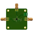
LT5560 Mixer Component Analysis
Thought for 1 min 58 sec
Here’s a summary of each non-ground net in your LT5560 mixer schematic, the components on that net (with their actual values), and the values recommended by the LT5560 datasheet (Table 3 and Table 7, Case 3 for 140 MHz matching):
Table
| Net Designator | Function | Components (Values) | Datasheet-Recommended Values (140 MHz Case) |
|---|---|---|---|
| Net 3 (IN+) | RF Input + | C2 22 pFL1 18 nH | Input-matching (Table 3): C = 22 pF, L = 18 nH |
| Net 6 (IN–) | RF Input – | C3 22 pFL3 18 nH | Input-matching (Table 3): C = 22 pF, L = 18 nH |
| Net 7 (LO+) | LO Input + | L4 18 nH | LO-matching (use same Table 3 values as RF input): C = 22 pF, L = 18 nH |
| Net 1 (LO–) | LO Input – | C1 22 pF | LO-matching (Table 3): C = 22 pF, L = 18 nH |
| Net 10 (OUT+) | Mixer Output + | C6 1.5 pFL5 220 nH | Output-matching (Table 7): C = 1.5 pF, L = 220 nH |
| Net 11 (OUT–) | Mixer Output – | C7 ––L6 220 nH | Output-matching (Table 7): L = 220 nH (no cap on – side for Case 3) |
| Net 14 (VCC) | Power Supply | C9 1 nF (bypass)C10 100 nF (additional decoupling)IC1 VCC pin | VCC bypass: 1 nF close to pin (datasheet §“VCC Pin Bypass”) |
| Net 2 (EN) | Enable Control | EN driven high (≥ 2 V) to enable; ties to VCC if unused | VEN ≥ 2 V to enable; tie to VCC if not used (datasheet §“EN Pin”) |
Notes:
- Input and LO matching networks both use the values from Table 3, Case 3 (for 140 MHz operation).
- Output matching uses Table 7, Case 3.
- VCC decoupling follows the datasheet’s “bypass with a 1 nF chip capacitor” recommendation; a parallel 100 nF improves broadband bypassing.
- All values and network configurations are taken directly from the LT5560 datasheet (Analog Devices 5560f).
Select input matching parts
Select output matching parts
Generate return loss plot
Annotate nets
Constraint placement