Chat
Welcome to Flux
Treat Flux like your intern. Tell it what you'd like to build and it'll get to work. You can also ask it questions, brainstorm ideas, and teach it your preferences. Learn More
Explain this part
Write a part description
Describe each pin
Operating conditions
Electrical max ratings
Part Specifications
Application circuits
Verify Part Details
Recommend similar parts
Check availability & lifecycle
Design a timer circuit using PIC16F887, with reset, stop, and start buttons

2y
To design a timer circuit using the PIC16F887 that includes reset, stop, and start buttons, you will need to consider both the hardware connections and the software programming for this microcontroller. Since we're focusing on the hardware design here, I will outline how to connect the buttons and suggest a basic approach for the software.
Assumptions:
- Reset, Stop, and Start Buttons: Normally open pushbuttons are used.
- I/O Pins: Using digital I/O pins for button inputs. Pins can be configured as input with internal pull-up resistors enabled in software to simplify circuitry.
- External Components: Minimal external components assumption (debouncing for buttons handled in software).
- Connect
VDDpins to a +5V power supply.- Connect VDD:P11 and VDD:P32 to +5V.
- Connect
VSSpins to ground.- Connect VSS:P12 and VSS:P31 to GND.
-
Reset Button (Assigned to
MCLRfor hardware reset feature):- Connect one side of the Reset button to
RE3/MCLR/Vpp:P1. - Connect the other side to +5V.
- Note: This pin is an active-low reset, so pulling it to VDD disables the reset. Pressing the button applies +5V directly, which normally wouldn't trigger a reset unless an external pull-down resistor is used to keep the pin normally at GND. Alternatively, this button could be connected to GND, and an external pull-up resistor used if software-controlled reset is not desired.
- Connect one side of the Reset button to
-
Stop Button (Using a general-purpose I/O):
- Connect one side of the Stop button to
RD0:P19(or another free digital I/O pin). - Connect the other side to GND.
- Enable internal pull-up resistor for
RD0in software.
- Connect one side of the Stop button to
-
Start Button (Using a different general-purpose I/O to differentiate from stop):
- Connect one side of the Start button to
RD1:P20(or another designated I/O pin). - Connect the other side to GND.
- Enable internal pull-up resistor for
RD1in software.
- Connect one side of the Start button to
- To use an LED or another indicator for timer status, connect the LED with a series resistor to a designated digital I/O pin and the other side to GND. Ensure the pin used is set as an output in your code.
- Connect
VDD:P11andVDD:P32to +5V. - Connect
VSS:P12andVSS:P31to GND. - Connect Reset button to
RE3/MCLR/Vpp:P1and the other side to +5V. - Connect Stop button to
RD0:P19and GND. - Connect Start button to
RD1:P20and GND.
- Initialize the PIC16F887 I/O pins for the buttons and any output indicators (e.g., LEDs).
- Poll the input pins connected to the Start and Stop buttons in your main loop, debouncing each button in software.
- Implement an interrupt service routine that increments a counter every timer tick when the timer is active. This will be your timer's base.
- Control the timer with Start and Stop buttons: start the timer counting on a Start button press, and stop it on a Stop button press.
- Reset Feature: Implement a feature that resets the counter to 0 on a Reset button press. This might be done with an external interrupt or polling, depending on how you've set up the Reset button. If connected directly to
MCLR, the reset functionality will be inherent but will restart the entire program, not just the counter.
Remember, the bulk of the timer functionality—such as counting time, debouncing button inputs, and responding to button presses—will be managed in the software you program into the PIC16F887. Ensure your code is robustly designed to handle these tasks efficiently.
2y
Someone is typing...
3
No files yet
Reviews

PIC16F887-I/P
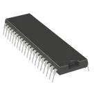
PIC series Microcontroller IC 8-Bit 20MHz 14KB (8K x 14) FLASH 40-PDIP
#Microcontroller #PIC16
#commonpartslibrary
Properties
Pricing & Availability
DPN | Stock | Qty 1 |
|---|---|---|
5 | 0–1K | $3.09–$3.3432 |
1 | 0 | $0.00 |
1 | 43 | $4.3249 |
1 | 2.1K | $3.19 |
1 | 10 | $4.25 |
15 | 0 | $0.00 |
Controls
Welcome 👋
Flux accelerates your PCB design with AI.
Create your account to start using this component and bring your ideas to life.
pailov
antonioseg
antonioseg