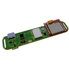
Pet Tracking Device Design

Yes — multiple cells in-line along the collar is a much better architecture.
Recommended battery topology:
  • Use parallel cells: 1S2P or 1S3P, not series.
  • That keeps the pack at the same safe single-cell Li-ion voltage range for the existing charger/SIM800L design.
  • It increases capacity while allowing cells to be placed end-to-end around the collar curve.
  • Each cell should have protection/fusing or a protected pack design, because parallel Li-ion cells need safe balancing and fault protection.
Runtime impact:
  • 1× 3500 mAh cell: ~20.8 mA average available for 7 days — borderline.
  • 2× 3500 mAh in parallel: ~41.7 mA average available — much safer.
  • 3× 3500 mAh in parallel: ~62.5 mA average available — strong margin.
  • With the earlier conservative estimate around 20.6 mA average, 2 cells should comfortably meet 7 days, assuming decent cellular/GPS signal and proper sleep firmware.
Design recommendation:
  • Use 1S2P 18650 cells as the baseline.
  • Keep 5-minute location updates as default.
  • Keep SIM800L/GPS sleep modes mandatory.
  • Mechanically, distribute the cells along the collar and connect them with flexible wiring or a rigid-flex harness; do not rely on the PCB itself to bend sharply around cylindrical cells.
I still can’t save this into the project because your access is comment-only, but the electrical direction is now clear: 1S2P 18650 pack + 5-minute reporting is the practical baseline.
Use 1S2P baseline
Explain pack wiring
Add protection details
Optimize power design
Check manufacturability
please explain what J1 does.

Someone is typing...
8
please explain what U2 does.

Someone is typing...
2
please explain what U2 does.

Someone is typing...
6
Check that none of the unconnected pins require pull-up or pull-down resistors t...

Someone is typing...
5
explain this project.

Someone is typing...
11
please explain what U5 does.

Someone is typing...
9
how much does this project cost

Someone is typing...
7
create a high level mermaid block diagram of U4. Include key component's manufac...

Someone is typing...
4
list all the parts used in this schematics along with its designator

Someone is typing...
10
please explain what L1 does.

Someone is typing...
14
U2
U1
GPS_RX
VUSB
SIM_RST
STM_RST
SWCLK
GPS_TX
SIM_TX
SIM_RX
SIM_RST
SCL
GPS_RX
SWCLK
SIM_TX
STM_RST
SDA
SWDIO
SWDIO
SDA
SCL
GPS_TX
SIM_RX
VBAT
3V3
R7
Resistance
1KΩ
P4
VBAT
VUSB
3V3
C3
Capacitance
4.7uF
R3
Resistance
22 Ω
L1
Inductance
22uH
J1
C2
Capacitance
10uF
R8
Resistance
10KΩ
3V3
3V3
J3
3V3
C1
Capacitance
10uF
3V3
P3
3V3
C4
Capacitance
4.7uF
C5
Capacitance
1uF
VBAT
VUSB
R4
Resistance
5KΩ
R2
Resistance
1KΩ
R6
Resistance
2KΩ
R5
Resistance
5KΩ
VBAT
R1
Resistance
1KΩ
D1
U5
U3
LED2
J4
BT1
LED1
J2
U4
IC1

No files yet

Documents

    Documents are markdown text files which describe project goals, capture details, or even simulation outputs.

    Assets

    Pet Tracker Reference Design.png

    Pet Tracker Reference Design.png

    Pet Tracker Reference DesignThumbnail

    Pet Tracker Device

    Pet Tracker Device thumbnail
    This is a Pet Tracker Reference Design based on STM32L4. Tracker connects with network by SIM800L module connected to the STM. Also MCU connected to the GPS by uart and send data to server #STM32 #GPS #G4 #G3 #LTE #IoT #Tracker #smartHomeDevices #referenceDesign #edge-computing #edgeComputing #stm #template #referenceDesign

    Pricing & Availability

    Distributor

    Qty 1

    Digi-Key

    $8.52–$9.78

    LCSC

    $13.91

    Mouser

    $8.23

    Controls