Chat

Welcome to Flux

Treat Flux like your intern. Tell it what you'd like to build and it'll get to work. You can also ask it questions, brainstorm ideas, and teach it your preferences. Learn More

Explain this part
Write a part description
Describe each pin
Operating conditions
Electrical max ratings
Part Specifications
Application circuits
Verify Part Details
Recommend similar parts
Check availability & lifecycle
draw 5a 12v dc out and 220v ac input smps draw

@copilot draw 5a 12v dc out and 220v ac input smps draw
2y
Definitely! It seems like you would like to design a Switched-Mode Power Supply (SMPS) with an input of 220V AC and an output of 5A, 12V DC using UC3842N controller. Please take note that designing power supply should be done with caution due to the high voltage and safety concerns.
For the sake of this design, I'll assume we're creating an isolated Flyback converter SMPS. This simple schematic should give you a good starting point:
  1. Connect your 220V AC input to a bridge rectifier (BR1), the output of the bridge rectifier should connect to a bulk capacitor (C1). This will convert the AC input to DC and smooth out the rectified signal.
  2. Connect VCC (Pin7) and GND (Pin5) of the UC3842 chip to the rectified DC from the bulk capacitor. This will provide the power to the UC3842.
  3. Connect a feedback resistor (R1) from the FB (Pin2) pin to the ground. This will provide feedback to the controller.
  4. The CS (Pin3) pin measures the current through the primary. Connect CS pin to a current sensing resistor (R2) which is connected between primary side of transformer and ground to measure the current.
  5. The RC (Pin4) pin should be connected to a Timing Capacitor (C2) and Timing Resistor (R3). This sets the oscillator frequency for the controller.
  6. The COMP (Pin1) pin is the error amplifier output and is made available for loop compensation. Connect a series RC compensator to filter out the noise.
  7. Connect OUT (Pin6) to the gate of a MOSFET (Q1).
  8. The primary winding of the transformer (T1) is connected between the MOSFET and the DC from the bridge rectifier.
  9. Connect the secondary winding of the transformer to a Diod (D1) and an output smoothing capacitor (C3) in series with a load resistor (RL) which simulate our load of 12V, 5A.
  10. The VREF (Pin8) should be connected to an optocoupler (U1) on the secondary side for feedback purposes. The optocoupler is also connected to the load with a Zener diode (D2) set to 12V to provide voltage reference to the optocoupler by sensing the output voltage.
This is a simplified view and the design may need to be tuned based on your particular requirements. Due to Flux's text-based limitation, I am unable to provide a drawn schematic. Make sure to calculate and choose appropriate component values based on your particular application and constraints. Be advised that this kind of project requires understanding and expertise in electronics and should be attempted with caution.
2y
Someone is typing...
2
GND
COMP
VREF
RC
CS
OUT
FB
VCC

No files yet

Documents

    Documents are markdown text files which describe project goals, capture details, or even simulation outputs.

    Assets

    kicad_mod

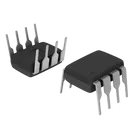
    DIP-8_W7.62mm-Footprint_V5.kicad_mod

    DIP-8_W7.62mm-Footprint_V5Footprint
    svg

    UC3842_DIP8

    defaultDefault
    DIP-8_W7.62mm-3D.step

    DIP-8_W7.62mm-3D.step

    DIP-8_W7.62mm-3D3D Model
    DIP-8_W7.62mm-removebg-preview.png

    DIP-8_W7.62mm-removebg-preview.png

    DIP-8_W7.62mm-removebg-previewThumbnail

    UC3842N

    UC3842N thumbnail
    Boost, Buck, Buck-Boost, Flyback, Forward Regulator Positive, Isolation Capable Output Step-Up, Step-Down, Step-Up/Step-Down - DC-DC Controller IC 8-PDIP

    Properties

    Integrated Circuit

    Texas Instruments

    UC3842N

    U

    Pricing & Availability

    DPN

    Stock

    Qty 1

    4

    0–926

    $0.9634–$0.9775

    5

    0

    $0.00

    2

    0–19

    $0.2325–$3.1542

    3

    0–512

    $0.00

    1

    50

    $1.13

    7

    26–900

    $0.5324–$1.30

    Controls