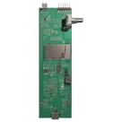
Schematic Design Review and Corrections

Below is a focused, schematic-level review based on what is explicitly present in your schematic and nets. Per Flux knowledge base guidance, I’m evaluating only observable connectivity, values, and properties—no speculation—while highlighting actionable corrections.
Electrical and logical issues
  • ESP32 IO0 shorted to MCLK via 0Ω links:
    • R24 (0Ω) ties Net 10 (ESP IO0/BOOT) to Net 43, and R16 (0Ω) ties Net 43 to Net 75 (MCLK), effectively bridging IO0 boot-strap to MCLK.
    • Corrections:
      • Remove or DNP R24 or R16 to eliminate the IO0–MCLK connection.
      • Add a pull-up from IO0 (Net 10) to 3V3 (e.g., 10kΩ Resistor) so the module boots normally; retain the BOOT switch to ground as implemented.
  • MCLK has no source:
    • Net 75 has IC2, C21, and R16 but is not driven by any MCU pin or oscillator. I2S_MCLK portals exist but are not connected.
    • Correction: Connect MCLK to its intended clock source (ESP32 pin or external clock). Remove the tie to IO0 (see above).
  • Codec line outputs not connected to amplifier inputs:
    • OUTP path: IC2C33 to GND and series C35 → Net 67 (floating; only [C35:P1] present).
    • OUTN path: IC2C32 to GND and series C34 → Net 66 (floating).
    • Corrections:
      • Connect C35 and C34 to the intended input nets (e.g., OUTP and OUTN).
  • Microphones not connected to codec:
    • MK1 (Net 73/Net 74) and MK2 (Net 112/Net 111) are single-node nets with no connection to IC2.
    • Corrections:
      • Wire MIC_P/MIC_N nets to IC2. If bias is required, connect the intended MICBIAS net accordingly.
  • Microphone power unpowered:
    • Net 77 supplies MK1 and MK2 but is not tied to any power rail.
    • Correction: Connect Net 77 to 3V3 (or the intended rail).
  • PFET gate floats when VBUS absent:
    • Q3 (Net 54) is only pulled to VBUS via R17. When VBUS is off, the gate is left floating.
    • Correction: Add a resistor from gate to battery (Net 15) or to source (Net 52) to define the PFET state with no VBUS.
  • Possible reverse current path (verify orientation):
    • Q3 is on Net 52 (system/LDO VIN) and Q3 is on Net 15 (battery). This orientation can allow body-diode backfeed from system to battery.
    • Correction: Verify PFET orientation for ideal-diode/high-side use; typical is source at the higher-potential source (battery) and drain toward the system.
  • Floating and unused nets to clean:
    • Net 67 (only C35), Net 66 (only C34), Net 22 (no connections), Net 73/74/111/112 (mics), and others like Net 6/40 (ESP analog inputs) appear not used or single-node.
    • Correction: Connect or remove as intended to avoid ambiguity.
Component-level review
  • ESP32 EN/BOOT handling:
    • EN has proper pull-up R1=10k and RC (C7, C11) to GND. Good.
    • IO0 is missing a pull-up to 3V3; it is instead linked to MCLK via 0Ω (see above).
    • Corrections:
      • Add IO0 pull-up (e.g., 10kΩ Resistor) to Net 10; break the tie to MCLK.
  • Codec control and clocks:
    • IC2 is strapped low via R8=10k to GND and is not MCU-controlled. There is a note “CE=0; I2C Address = 0x18.” If address/config strap is intended, ok; otherwise route CE to a GPIO.
    • Multiple 33Ω series resistors present on digital audio lines (R10, R11, R12, R13, R14, R15). Good.
    • Small shunt capacitors to GND on clock/data lines (C21, C22, C23, C24, C25, C19, C20) create RC filters with the 33Ω series elements; confirm this is intentional for EMI. If not, remove/shrink these shunt caps.
  • USB-C and UART bridge:
    • CC resistors correctly present: R2=5.1k to GND for CC1 and R3=5.1k for CC2.
    • ESD/TVS protection present: D2 on D+/D- and VBUS.
    • No series resistors on D+/D- between USB1 and IC1 observed; if the bridge or layout requires them, add per IC guidance.
    • R18=100k from VBUS to GND provides a continuous bleed; confirm that constant VBUS load is desired.
  • Battery charger and indicators:
    • U3 wiring is consistent: VCC/CE to VBUS (Net 53), BAT to Net 15/battery connector BAT, charge/status LEDs CHRG/STDB via R23/R22.
    • PROG (R20=1k) and TEMP (R21=0Ω) tied appropriately; verify TEMP strap per your device requirements.
  • LDO and decoupling:
    • U1 has input cap C5 and output bulk/decoupling (C3, C4, C1, C2, C6, C8). Good.
Power and signal integrity
  • PFET high-side control ambiguity:
    • With Q3 floating when VBUS is absent, system power behavior on battery is undefined. Add a defined pull (see above).
  • MCLK integrity:
    • C21 shunts MCLK to GND; unless intentionally filtering, this adds capacitive load. Once MCLK is sourced, verify signal margins with the 33Ω series ([R16 path removed]).
  • USB shield bonding:
    • USB1 is tied directly to the main ground net (“”); confirm this is intended for your EMI/ESD strategy.
Schematic best practices and clarity
  • Unlabeled nets:
    • The main ground net is unnamed (“”) and many signals are “Net XX.” Assign explicit net labels for key rails and signals (GND, 3V3, BAT, MCLK, LRCK, BCLK, SD, etc.) to improve readability and reduce mistakes.
  • Orphan portals and placeholders:
    • Several net portals (e.g., ESP32_SDA, ESP32_SCL, I2S_MCLK) don’t tie into active nets. Remove or connect as intended.
    • Clean up Net 22 and other single-node nets if unused.
Actionable corrections summary
  1. Break the IO0–MCLK short by DNP/removing R24 or R16; add IO0 pull-up to 3V3 (e.g., 10kΩ Resistor).
  2. Connect MCLK (Net 75) to its intended source; review/removal of C21 if not required.
  3. Connect C35 and C34 to OUTP/OUTN inputs; remove floating nets 66/67.
  4. Wire MK1/MK2 MIC_P/MIC_N to IC2; power Net 77 from 3V3.
  5. Add a defined pull for Q3 so it’s not floating without VBUS; verify PFET orientation to avoid body-diode backfeed to battery.
  6. If unneeded, remove shunt caps on audio/control lines (C22, C24, C25, C19, C20, C21).
  7. Confirm intent of R18=100k VBUS-to-GND bleed; remove if not needed.
  8. Name key nets and remove unused portals/nets to improve clarity and reduce risk.
If you want, I can prepare a precise set of edits (remove jumpers, add pull-up, connect MCLK/OUTP/OUTN/MICs, add PFET gate pull) as a small batch for you to review before we execute.
Break IO0–MCLK link
Find pull-up resistor
Add IO0 pull-up
Connect MCLK to ESP32
Wire codec outputs
USB1
AI Brick Phone AMP
U1
Manufacturer Part Number
AMS1117-3.3
IC2
D2
R39
Resistance
33 Ω
R40
Resistance
33 Ω
R16
Resistance
0 Ω
R35
Resistance
33 Ω
R9
Resistance
2.2kΩ
R47
Resistance
2kΩ
R10
Resistance
33 Ω
R15
Resistance
33 Ω
R11
Resistance
33 Ω
R41
Resistance
0 Ω
R13
Resistance
33 Ω
R48
Resistance
220 Ω
Exclude from BOM
true
R12
Resistance
33 Ω
R5
Resistance
0 Ω
R55
Resistance
0 Ω
R34
Resistance
33 Ω
R50
Resistance
0 Ω
R49
Resistance
220 Ω
R7
Resistance
0 Ω
R53
Resistance
0 Ω
R24
Resistance
0 Ω
R36
Resistance
10kΩ
R46
Resistance
2kΩ
R52
Resistance
0 Ω
R33
Resistance
33 Ω
R25
Resistance
0 Ω
R54
Resistance
0 Ω
R14
Resistance
33 Ω
R26
Resistance
33 Ω
R19
Resistance
0 Ω
R18
Resistance
100kΩ
R6
Resistance
2.2kΩ
R17
Resistance
100kΩ
R38
Resistance
10kΩ
R37
Resistance
10kΩ
R8
Resistance
10kΩ
R20
Resistance
1kΩ
Tolerance
1 %
D1
C4
Capacitance
10uF
C3
Capacitance
10uF
C24
Capacitance
22pF
C29
Capacitance
0.1uF
C45
Capacitance
0.1uF
C25
Capacitance
22pF
C21
Capacitance
22pF
C11
Capacitance
0.1uF
C33
Capacitance
22pF
C23
Capacitance
22pF
C8
Capacitance
10uF
C37
Capacitance
22pF
C38
Capacitance
22pF
C6
Capacitance
0.1uF
C7
Capacitance
0.1uF
C17
Capacitance
1uF
C31
Capacitance
1uF
C44
Capacitance
10uF
C16
Capacitance
1uF
C41
Capacitance
1uF
C43
Capacitance
1uF
C15
Capacitance
1uF
C30
Capacitance
0.1uF
C13
Capacitance
1uF
C2
Capacitance
0.1uF
C27
Capacitance
0.1uF
C40
Capacitance
1uF
C1
Capacitance
0.1uF
C14
Capacitance
0.1uF
C36
Capacitance
1uF
C19
Capacitance
22pF
C12
Capacitance
0.1uF
C35
Capacitance
1uF
C42
Capacitance
1uF
C32
Capacitance
22pF
C20
Capacitance
22pF
C22
Capacitance
22pF
C28
Capacitance
1uF
C34
Capacitance
1uF
C39
Capacitance
1uF
CHRG
R32
Resistance
10kΩ
Q3
R31
Resistance
10kΩ
R1
Resistance
10kΩ
R21
Resistance
0 Ω
D3
ESP1
PWR
R56
Resistance
10kΩ
D5
R2
Resistance
5.1kΩ
R4
Resistance
1kΩ
R30
Resistance
10kΩ
R3
Resistance
5.1kΩ
R43
Resistance
10kΩ
R58
Resistance
10kΩ
R57
Resistance
10kΩ
R45
Resistance
1.6kΩ
D4
R44
Resistance
1.6kΩ
STDB
R22
Resistance
1kΩ
R23
Resistance
1kΩ
Q4
R51
Resistance
10kΩ
R42
Resistance
10kΩ
3V3
C76
Capacitance
0.001uF
C26
Capacitance
10uF
H1
C18
Capacitance
10uF
D6
SW1
U3
TX
C9
Capacitance
10uF
RST
Q1
L1
U2
EN
H2
C5
Capacitance
10uF
GND
H4
D7
BOOT
C77
Capacitance
0.001uF
IO0
H3
C75
Capacitance
0.001uF
Q2
RX
J4
BAT
CE=0; I2C Address = 0x18
J1
BATTERY
Line 1
3.7V, 2000mAh
Card1
IC1

No files yet

Documents

    Documents are markdown text files which describe project goals, capture details, or even simulation outputs.

    Assets

    AI Brick Phone image.png

    AI Brick Phone image.png

    AI Brick Phone imageThumbnail

    Tiny airwires make me crazy Error

    Tiny airwires make me crazy Error thumbnail

    Pricing & Availability

    Distributor

    Qty 1

    Arrow

    $2.15–$4.22

    Digi-Key

    $3.95–$18.64

    LCSC

    $3.02–$3.84

    Mouser

    $14.25

    TME

    $7.70

    Verical

    $2.67–$529.97

    Controls