PCB Design for RGB NeoPixel Module
0:36
Below is a summary of the changes we're about to implement in your schematic:
-
WS2812B NeoPixels:
- Three WS2812B NeoPixels added as U1, U2, and U3.
- Each LED gets its own 0.1µF decoupling capacitor (C1 for U1, C2 for U2, C3 for U3).
-
JST-GH 3-Pin Connector:
- A JST-GH 3-pin male connector is added as J1.
- Pin connections:
- +5V from J1 to all WS2812B VDD pins.
- GND from J1 to all WS2812B GND (using a Ground component as needed).
- Data from J1 to the Data IN of U1, then chaining from U1 to U2 and U2 to U3.
You can use the Apply changes button to apply these schematic updates.
PCB Layout Arrangement Guidelines
After updating the schematic, here are some suggestions for arranging the components on a compact PCB (less than 15 mm in diameter):
-
Component Placement:
- WS2812B LEDs: Arrange the three WS2812B components in a tight, possibly angular or circular pattern around the center. This optimizes space and keeps the PCB radius below 15 mm.
- JST Connector (J1): Place the JST connector along one edge of the layout to expose the pins for easy mating with the Pixhawk’s AUX connector.
- Decoupling Capacitors: Position each capacitor immediately adjacent to its respective WS2812B to ensure effective noise filtering. This is vital when the board experiences vibration and proximity to heat sources.
-
Routing & Mechanical Considerations:
- Power Traces: Use wide traces for the 5V and GND connections to ensure robust power delivery. Run these traces radially from the JST connector.
- Data Trace: Route the data trace with minimal bends and keep it isolated from noisy power traces.
- Design for Vibration: Secure all components firmly, and consider the use of small mounting holes if needed to mechanically fasten the board under the motor.
- Thermal Clearance: Ensure some spacing between components to allow for heat dissipation given the proximity to the motor.
If you’re ready, click the Apply changes button to update the schematic. Once applied, we can refine the PCB layout further with these suggestions in mind.
Verify layout plan
Optimal PCB placement
Guidance for layout
360 days
Ready.
To get started, talk to Flux or create a New Document.
Reviews
Documents
Documents are markdown text files which describe project goals, capture details, or even simulation outputs.
Assets
kicad_mod
JST_SH_SM04B-SRSS-TB_1x04-1MP_P1.00mm_Horizontal-Footprint-S.kicad_mod
Footprint-S
SM04B-SRSS-TB image.png
SM04B-SRSS-TB imageThumbnail
Conn_01x04
defaultDefaultstep
PRT-14417--3D.step
3D3D ModelQWIIC I2C JST Connector
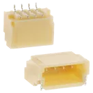
SparkFun's Qwiic Connect System uses 4-pin JST connectors to quickly interface development boards with sensors, LCDs, relays and more.
Connector Header Surface Mount, Right Angle 4 position 0.039" (1.00mm)
Properties
Connector
JST Sales America Inc.
SM04B-SRSS-TB
J
Pricing & Availability
Distributor | Qty 1 |
|---|
Controls
Welcome 👋
Flux accelerates your PCB design with AI.
Create your account to start using this component and bring your ideas to life.