Treat Flux like your intern. Tell it what you'd like to build and it'll get to work. You can also ask it questions, brainstorm ideas, and teach it your preferences. Learn More
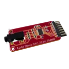
This project is focused on a reference design for the PCM5102A, which is a 2VRMS DirectPath™, 112dB Audio Stereo DAC with a 32-bit, 384kHz PCM Interface. Let's break down the key components and connections in this design:
Key Components:
PCM5102: This is the main DAC chip from Texas Instruments. It converts digital audio data into analog audio signals.
Capacitors (C1 to C14): Various capacitors in this design serve filtering and decoupling purposes to stabilize power supplies and improve signal integrity.
Resistors (R3, R4): These resistors are used to set output characteristics or as part of filtering networks.
Ferrite Beads (FB1, FB2): These are used for electromagnetic interference (EMI) suppression.
Connectors (J1, J2): Used for connecting external signals or power sources to the board.
Power Supplies:
+3.3V and +3.3VA: These nets provide power to the DAC (IC1) and other components on the board.
AGND and GND: These are ground connections used for analog and digital sections of the circuit, respectively.
Key Nets:
Digital Audio Interface: The DAC interfaces with digital audio sources via the following nets:
DIN: Digital audio data input
BCK (Bit Clock): Clock signal for data shifting
LRCK (Left-Right Clock): Determines which channel data is sent to
SCK (System Clock): High-frequency clock signal for DAC operation
Audio Outputs:
OUTL and OUTR: These nets represent the left and right analog audio outputs from the DAC.
Mute Control: The MUTE net controls the muting of the DAC, connected to the XSMT pin on the PCM5102.
Additional Notes:
This design contains references to mounting holes, likely used for PCB enclosure or securing.
The designators like IC1, C7, etc., are used to identify components on the schematic and PCB layout.
Overall, this project appears to be a detailed implementation of a digital-to-analog conversion circuit, focusing on audio applications. If you have any specific questions or need help connecting certain parts, feel free to ask!
1y
Someone is typing...
2
DIN
AGND
LRCK
AGND
OUTL
+3.3VA
SCK
AGND
OUTR
BCK
+3.3VA
+3.3V
MUTE
OUTR
DIN
OUTL
+3.3VA
AGND
SCK
+3.3V
+3.3V
AGND
AGND
+3.3VA
LRCK
BCK
AGND
+3.3V
AGND
MUTE
IC1
J1
C5
Capacitance
10uF
R4
Resistance
470 Ω
C7
Capacitance
10uF
FB1
C9
Capacitance
10uF
C13
Capacitance
2.2uF
C8
Capacitance
0.1uF
C3
Capacitance
10uF
FB2
C1
Capacitance
2.2nF
C14
Capacitance
2.2uF
R3
Resistance
470 Ω
C2
Capacitance
2.2nF
C4
Capacitance
0.1uF
C10
Capacitance
0.1uF
C6
Capacitance
0.1uF
H2
J2
H1
No files yet
Reviews
Documents
Documents are markdown text files which describe project goals, capture details, or even simulation outputs.
jharwinbarrozo
copilot
-
PCM5102: This is the main DAC chip from Texas Instruments. It converts digital audio data into analog audio signals.
-
Capacitors (C1 to C14): Various capacitors in this design serve filtering and decoupling purposes to stabilize power supplies and improve signal integrity.
-
Resistors (R3, R4): These resistors are used to set output characteristics or as part of filtering networks.
-
Ferrite Beads (FB1, FB2): These are used for electromagnetic interference (EMI) suppression.
-
Connectors (J1, J2): Used for connecting external signals or power sources to the board.
Power Supplies:-
+3.3V and +3.3VA: These nets provide power to the DAC (IC1) and other components on the board.
-
AGND and GND: These are ground connections used for analog and digital sections of the circuit, respectively.
Key Nets:-
Digital Audio Interface: The DAC interfaces with digital audio sources via the following nets:
- DIN: Digital audio data input
- BCK (Bit Clock): Clock signal for data shifting
- LRCK (Left-Right Clock): Determines which channel data is sent to
- SCK (System Clock): High-frequency clock signal for DAC operation
-
Audio Outputs:
- OUTL and OUTR: These nets represent the left and right analog audio outputs from the DAC.
-
Mute Control: The MUTE net controls the muting of the DAC, connected to the XSMT pin on the PCM5102.
Additional Notes: