Chat

Welcome to Flux

Treat Flux like your intern. Tell it what you'd like to build and it'll get to work. You can also ask it questions, brainstorm ideas, and teach it your preferences. Learn More

Explain this part
Write a part description
Describe each pin
Operating conditions
Electrical max ratings
Part Specifications
Application circuits
Verify Part Details
Recommend similar parts
Check availability & lifecycle
explain this project.

@copilot explain this project.
2y
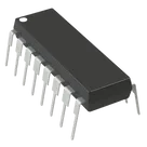
This project involves setting up a circuit schematic for an L293D motor driver IC (Integrated Circuit), which is commonly used to control DC motors, stepper motors, relay drives, and solenoids in a bipolar manner. The L293D IC can drive up to four loads, and it's characterized by its supply voltage range of 4.5V to 36V, available in a 16-DIP (Dual In-line Package). It's a part of the Common Parts Library, indicating it's widely used and recognized for its utility in motor-driving applications. The manufacturer listed is STMicroelectronics, a well-known entity in the semiconductor industry.
Below is a breakdown of the components and pins specified in the project description in terms of their roles within the L293D IC:
  • 1Y, 2Y, 3Y, 4Y (Designators): These pins likely correspond to the outputs to the motors or loads. "Y" typically denotes the output in IC schematics. The numbers indicate they are for different channels or motor outputs.
  • 1A, 2A, 3A, 4A (Designators): These pins are inputs from the control unit (like a microcontroller). "A" likely stands for input. Each "A" pin controls its corresponding "Y" output.
  • EN1,2 and EN3,4 (Designators): EN stands for Enable. These pins are used to enable or disable the driver channels. EN1,2 likely controls channels 1 and 2, while EN3,4 controls channels 3 and 4.
  • GND (Designators): Multiple Ground pins for the circuit. It's common for ICs, especially power ICs, to have several ground pins to handle the return current effectively.
  • VCC1 and VCC2 (Designators): These are the power supply pins for the IC. VCC1 might be for the logic part of the IC, and VCC2 for the motor power supply. This division allows for different voltages to be used for the IC logic and motor drive components if necessary.
This breakdown assumes typical conventions for pin designations and common configurations for the L293D IC but doesn't cover the specifics of how each component is to be connected within the circuit. The next steps would involve connecting these pins to motors, power supply, ground, and control signals (from a microcontroller or another control unit) according to the specific requirements of the intended application.
However, it's notable that the project details don't include any specifics about the control logic or power supply requirements beyond the pin designations. These would be crucial for completing the circuit design and ensuring it functions as intended.
2y
Someone is typing...
3

No files yet

Documents

    Documents are markdown text files which describe project goals, capture details, or even simulation outputs.

    Assets

    kicad_mod

    DIP-16_W7.62mm-Footprint-S.kicad_mod

    Footprint-SFootprint
    step

    DIP-16_W7.62mm.step

    2-3D
    DIP-16_W7.62mm-removebg-preview.png

    DIP-16_W7.62mm-removebg-preview.png

    DIP-16_W7.62mm-removebg-previewThumbnail

    L293D

    L293D thumbnail
    Bipolar Motor Driver - Parallel IC 4.5-36V 16-DIP #CommonPartsLibrary #MotorDriver #IntegratedCircuit #L293

    Properties

    Integrated Circuit

    STMicroelectronics

    L293D

    U

    Parametric

    Pricing & Availability

    Distributor

    Qty 1

    Controls