JLCPCB Component Availability Check

38 days
How many PCB layers does this project have?
Thought for 4 sec
38 days
I’ll check the project’s PCB stackup/layer settings and report the layer count.
Thought for 36 sec
38 days
This project uses a 4-layer PCB stackup.
Signal/copper layers:
- Top Copper
- Mid-Layer 1
- Mid-Layer 2
- Bottom Copper
The stackup is named “Standard 4 Layer.”
38 days
What are the dimensions of the PCB in mm?
Thought for 19 sec
38 days
The PCB board size is 31 mm × 65 mm.
It is a rectangular 4-layer PCB with an area of 2015 mm².
Review size and layout
Run DRC review
Suggest board size
Explain density warning
Optimize placement
what is this

@copilot what is this
2y
This text describes an electronic project focused on creating a controller module that uses the ESP32-WROOM-32E microcontroller and the MAX3485 driver to communicate with Modbus devices via RS485 protocol. Here's a detailed breakdown:
-
Main Components:
- ESP32-WROOM-32E: A powerful microcontroller from Espressif Systems that provides Wi-Fi and Bluetooth capabilities.
- MAX3485: A Maxim Integrated RS485/RS422 transceiver, facilitating communication over an RS485 network.
- CH340C: A USB to serial converter chip, enabling USB connectivity for programming and communication with the ESP32.
- AMS1117-3.3: A voltage regulator that provides a stable 3.3V output from a higher voltage input.
- USB-C Connector (USB1): Used for power input and data transfer.
- Diodes, Resistors, and Capacitors: Essential components used for protection, voltage regulation, filtering, and interfacing.
-
Features & Functions:
- The project incorporates RS485 communication via Modbus protocol, allowing the module to control or interact with a variety of devices that support this standard.
- The inclusion of a USB-C port for power and programming flexibility.
- Use of the CH340C chip for USB to serial conversion facilitates easy programming of the ESP32.
- The AMS1117-3.3 voltage regulator ensures the ESP32 operates at a stable voltage.
- The project also includes various GPIO (General Purpose Input/Output) pins and nets connected to various components and the ESP32 for interfacing and control purposes.
-
Connectivity:
- RS485 Communication: Managed by the MAX3485 transceiver, connected to the ESP32 for Modbus communication.
- USB-C Interface: For programming the ESP32 and power supply.
-
Miscellaneous:
- The schematic contains nets, which are symbolic representations of connections between components. Each net in the schematic is associated with specific components and pins, indicating how they are electrically connected.
- The design incorporates various protective elements like diodes (e.g., 1N5819HW-7-F for reverse voltage protection) and ESD protection components (e.g., SM712).
- Several resistors and capacitors are used throughout the design for filtering, pull-up/pull-down functions, and ensuring signal integrity.
- Power supply management is highlighted with dedicated nets and components for 3.3V and 5V supply lines.
This text is essentially a detailed description of an electronics scheme for a specific hardware project, providing enough information for understanding the key components, their arrangement, and overall functionality without needing visual schematics.
2y
Someone is typing...
5
I wanna add 2 status leds

@copilot I wanna add 2 status leds
2y
Adding status LEDs to your project is a great idea! To integrate two status LEDs into your design, follow these steps:
-
Choose LED designators and resistors:
- For simplicity, let's use the designators
LED1andLED2for the LEDs. - Use resistors
R10andR11to limit the current through the LEDs. Assume typical values like 330Ω.
- For simplicity, let's use the designators
-
Connect the LEDs to GPIO pins:
- We'll assume you want to control the LEDs using two available GPIO pins from the ESP32-WROOM-32E.
Let's proceed with the following steps:
Step 1: Add the LEDs and resistors
- LEDs: Choose any standard LED with a forward voltage around 2V.
- Resistors: Use 330Ω resistors to limit the current to around 10mA.
-
For
LED1:- Connect the anode (A) of
LED1toGPIO32. - Connect the cathode (K) of
LED1to one end ofR10. - Connect the other end of
R10toGND.
- Connect the anode (A) of
-
For
LED2:- Connect the anode (A) of
LED2toGPIO33. - Connect the cathode (K) of
LED2to one end ofR11. - Connect the other end of
R11toGND.
- Connect the anode (A) of
-
LED1:
- Connect
LED1:AtoU2:IO32. - Connect
LED1:KtoR10:P1. - Connect
R10:P2toGND.
- Connect
-
LED2:
- Connect
LED2:AtoU2:IO33. - Connect
LED2:KtoR11:P1. - Connect
R11:P2toGND.
- Connect
These connections will let you control the status LEDs using the ESP32's GPIO pins. If you have specific preferences for different GPIOs or resistor values, feel free to let me know!
2y
Someone is typing...
14
quiero un circuito que conecte un modulo max485 con una placa esp32

@copilot quiero un circuito que conecte un modulo max485 con una placa esp32
2y
Para conectar un módulo MAX485 con una placa ESP32, debes realizar las siguientes conexiones básicas:
-
Alimentación:
- MAX485: VCC pin a 3.3V del ESP32.
- MAX485: GND pin a GND del ESP32.
-
Comunicación:
- MAX485: RO (Receiver Out) pin al pin RX de ESP32 U2:RXD0/IO3.
- MAX485: DI (Driver In) pin al pin TX de ESP32 U2:TXD0/IO1.
- MAX485: ~RE (Receiver Enable) pin al pin que desees configurar para control RE del ESP32 por ejemplo, U2:IO4.
- MAX485: DE (Driver Enable) pin al mismo pin que ~RE para controlar ambos con el mismo pin del ESP32.
-
Bus RS485:
- MAX485: A y B a las líneas diferenciales del bus RS485.
En resumen, estas conexiones se podrían describir de la siguiente manera:
-
Alimentación:
- Conectar IC3:VCC a U2:VDD (3.3V)
- Conectar IC3:GND a U2:GND
-
Comunicación:
- Conectar IC3:RO a U2:RXD0/IO3
- Conectar IC3:DI a U2:TXD0/IO1
- Conectar IC3:~RE a U2:IO4
- Conectar IC3:DE a U2:IO4
-
Bus RS485:
- Conectar IC3:A a la línea A del bus RS485
- Conectar IC3:B a la línea B del bus RS485
Aquí tienes en formato de lista, como lo requiere el formato que mencionaste:
- Conectar IC3:VCC a U2:VDD
- Conectar IC3:GND a U2:GND
- Conectar IC3:RO a U2:RXD0/IO3
- Conectar IC3:DI a U2:TXD0/IO1
- Conectar IC3:~RE a U2:IO4
- Conectar IC3:DE a U2:IO4
- Conectar IC3:A a la línea A del bus RS485
- Conectar IC3:B a la línea B del bus RS485
Asegúrate de tener resistencia de terminación de 120 ohmios en tus líneas diferenciales A y B si están muy extendidas o si la señal es débil.
2y
Someone is typing...
9
list all ICs and the decoupling capacitors attached to each.
Ensure to include a...

@copilot list all ICs and the decoupling capacitors attached to each.
Ensure to include all ICs present in the design, including digital ICs, power converters, LDOs, etc.
For every IC, clearly state:
- What power net the decoupling capacitors are attached to. What is the stated voltage of that net.
- The voltage rating and value of the attached decoupling capacitors.
- Signal with the expression “[WARNING]” if any of the following conditions are met: no decoupling capacitors are attached; the voltage of the power net is higher than the voltage rating of the capacitor; No voltage range was stated for the capacitor. Give a separate “[WARNING]” for each condition. Signal with the expression “[OK]” if none of those conditions are met
- Express the result in a markdown-formatted table
1y
To address your request, let's first identify the ICs and their corresponding decoupling capacitors in your project's design. The list of integrated circuits (ICs) in the project are:
Let’s go through each IC and identify the relevant power net and decoupling capacitors:
Table
| IC | Power Net | Net Voltage | Decoupling Capacitors | Capacitance | Voltage Rating | Status |
|---|---|---|---|---|---|---|
| ESP32-WROOM-32E | +3V3 | 3.3V | C1, C2, C4, C3, C8 | 0.1uF, 0.1uF, 10uF, 10uF, 10uF | Not stated | [WARNING] Missing voltage rating |
| MAX3485CSA+ | +3V3 | 3.3V | C6 | 0.1uF | Not stated | [WARNING] Missing voltage rating |
| AMS1117-3.3 | +5V | 5V | None | N/A | N/A | [WARNING] No decoupling capacitors |
| CH340C | +3V3 | 3.3V | C12, C11 | 0.1uF, 0.1uF | Not stated | [WARNING] Missing voltage rating |
- ESP32-WROOM-32E: Has multiple decoupling capacitors, but the voltage rating for each is not provided.
- MAX3485CSA+: Has one decoupling capacitor with no stated voltage rating.
- AMS1117-3.3: No decoupling capacitors are specified. According to the datasheet, this IC requires an output capacitor[1] which is not included.
- CH340C: Has two decoupling capacitors, but the voltage rating for each is not provided.
Ensure to add the necessary voltage ratings for all capacitors and include a decoupling capacitor for the AMS1117-3.3 to prevent operational issues.
[1] Page 4
1y
Someone is typing...
15
please explain what TERM does.

2y
In the context of RS485 communication,
Purpose of Termination Resistor
TERM typically refers to a termination resistor. Termination resistors are used to match the impedance of the transmission line to prevent signal reflections, which can cause data errors or signal degradation. Here's a more detailed explanation:- Impedance Matching: RS485 networks generally use twisted pair cables, and the characteristic impedance of these cables is usually around 120 ohms. By adding a termination resistor (typically 120 ohms) at the ends of the communication line, the impedance is matched, preventing reflections.
- Signal Integrity: By minimizing reflections, the quality of the signal is maintained, ensuring reliable communication over long distances.
- Ends of the Bus: Termination resistors should be placed at both ends of the RS485 bus. This placement helps to absorb the signal energy and prevents it from reflecting back into the line.
In your project, the termination resistor can be represented by the following components:
- Designator:
TERM - Terminating Points: Connect the termination resistor across the differential lines, typically labeled as
AandB.
Here's an example of how it might look in connections:
Potential connections might be:
These connections will place the termination resistor across the RS485 differential lines, ensuring impedance matching and reducing signal reflection.
Confirmation in Your Project
From your project details, you have:
## Designator: TERM
Pins: 1 (name: P1),2 (name: P2)
Element Properties:
Exclude from BOM: true
Designator Prefix: SJ
This indicates a jumper (
Summary
SJ), which might be used to enable or disable the termination. To include or exclude the termination resistor based on layout requirements.- Function: Reduce signal reflection by impedance matching.
- Placement: At the ends of the RS485 communication line.
- Implementation: Use a 120-ohm resistor across
AandBlines.
If you need more details or further assistance on any other part of your schematic, feel free to ask!
2y
Someone is typing...
12
how do I use Flux?
@copilot how do I use Flux?
2y
To use Flux effectively, you can follow these general steps and explore the various resources available to deepen your understanding and skills:
-
First Project: The best way to get started with Flux is to dive into creating your first project. This will help you familiarize yourself with the Flux interface and its basic functionalities. You can access a guide for starting your first project in the documentation or tutorials[1].
-
Tutorials: Flux offers detailed tutorials that cover everything from the basics to more advanced features. These tutorials are designed to help you understand how to design electronic schematics and lay out PCBs efficiently[1].
-
Reference Materials: For detailed information about specific elements of Flux, such as component placement, wiring, and layer management, refer to the reference section in the documentation. This is a great resource for finding in-depth information about Flux's capabilities[1].
-
YouTube: Explore Flux's library of video tutorials, crash courses, and recorded events on their YouTube channel. These videos can provide visual guidance on how to use Flux and often cover common use cases and complex projects[2].
-
Slack Community: Join the Flux Slack community to connect with other engineers, designers, and hardware enthusiasts. This platform allows you to ask questions, share your projects, and get direct support from the Flux team[3].
-
Live Support: If you need direct assistance or have specific questions, Flux's live support is available. Go to the contact section on their homepage to find how to get in touch[2].
Start by experimenting with placing components and connecting them on the schematic editor, then move on to laying out your PCB. Using these resources and exploring Flux by working on projects will enhance your understanding and proficiency with the tool.
2y
Someone is typing...
4
create a high level mermaid block diagram of U2. Include key component's manufac...
@copilot create a high level mermaid block diagram of U2. Include key component's manufacturer part number in each block whenever possible.
2y
Someone is typing...
10
para que sirve
2y
Vamos a desglosar el propósito de cada elemento principal de tu proyecto de controlador Modbus con ESP32 y MAX3485:
-
ESP32-WROOM-32E: Este es el microcontrolador principal que maneja toda la lógica y control del proyecto. Tiene capacidades de Wi-Fi y Bluetooth, lo que lo hace versátil para aplicaciones de IoT.
-
MAX3485: Este es un transceptor RS485, que permite la comunicación serial en largas distancias y con alta inmunidad al ruido. Es esencial para la comunicación Modbus en tu proyecto.
-
USB-C Port: Proporciona alimentación y también permite la programación y depuración del ESP32 a través de una conexión USB.
-
Voltage Regulator (AMS1117-3.3): Regula la tensión de entrada (5V del puerto USB) a 3.3V, que es lo que requiere el ESP32 para funcionar correctamente.
-
CH340C: Este chip convierte señales USB a serial TTL. Permite la programación del ESP32 a través del puerto USB.
-
Alimentación y Regulación:
- Conecta USB1:VBUS a U1:VIN.
- Conecta U1:VOUT a +3V3:P1.
- Conecta U1:GND a GND:P1.
-
ESP32 a RS485:
- Conecta U2:TXD0/IO1 a IC3:DI.
- Conecta U2:RXD0/IO3 a IC3:RO.
- Conecta U2:IO4 a IC3:DE y IC3:~RE (control de transmisión).
-
Interfaz USB a Serial:
- Conecta USB1:DP1 a IC1:UD+.
- Conecta USB1:DN1 a IC1:UD-.
- Conecta IC1:TXD a U2:RXD0/IO3.
- Conecta IC1:RXD a U2:TXD0/IO1.
Este módulo puede ser usado para controlar dispositivos que usen el protocolo Modbus, y también puede ser programado y monitoreado a través de USB gracias al conversor CH340C. La regulación de voltaje asegura que el ESP32 y otros componentes reciban una tensión estable de 3.3V para su operación adecuada.
¿Hay algo más específico que necesitas saber sobre alguna parte del proyecto o su funcionalidad?
2y
Someone is typing...
13
explain this project.

@copilot explain this project.
2y
This project is designed as a controller module leveraging the ESP32-WROOM-32E module for its processing and WiFi capabilities, and the MAX3485 communication chip to interface with Modbus devices over RS485. Its primary purpose is to enable communication, control, and data acquisition from various devices and sensors that operate on the Modbus protocol, making it quite versatile in applications ranging from industrial control systems to home automation.
Here's a breakdown of key aspects and components of the project:
ESP32-WROOM-32E
- Primary Controller: Acts as the brain of the project with WiFi capabilities. It handles processing, execution of the logic, and communication with connected Modbus devices through the RS485 interface.
- Pins and Functions: It's connected to various GPIOs, power supply nets, and communication interfaces like RX/TX for serial communication.
- RS485 Communication: Responsible for translating data from the ESP32's TTL logic level to the RS485 differential signal, enabling robust long-distance communication characteristic of RS485.
- Power and Data: The USB-C port not only supplies power to the module but also serves as a data connection point, probably for programming the ESP32 and potentially for data transfer purposes.
- Voltage Regulator: Ensures a stable 3.3V power supply from a higher voltage source (likely from the USB-C connection) for powering the ESP32 and other 3.3V components.
- USB to Serial Converter: Facilitates the communication between a computer and the ESP32 module for programming or serial debugging.
- Dual Voltage Rails: Utilizes +3V3 and +5V power nets to accommodate different component requirements. The +3V3 line powers the logic and ICs, while the +5V might be used for USB power and any components requiring higher voltages.
- Capacitors (C1, C2, C3...): Used across the project for decoupling and noise filtering purposes.
- Resistors (R1, R2, R3...): Serve various purposes including pull-up/pull-down resistors for signal integrity, and biasing for the MAX3485.
- Interface Ports: Contains a USB Type-C port for power and data, and an RS485 port (marked as "A RS485 B") for Modbus communication.
- All the components and the design itself seem to adhere to the Creative Commons Attribution 4.0 International License, promoting openness and sharing in the hardware design community.
The project's schematic is structured to facilitate Modbus communication over RS485 using the ESP32 as a controller, which is suitable for a wide range of applications that require remote control and data acquisition over a reliable, noise-resistant communication protocol.
2y
Someone is typing...
2
create a high level mermaid block diagram of U2. Include key component's manufac...

@copilot create a high level mermaid block diagram of U2. Include key component's manufacturer part number in each block whenever possible.
2y
To represent the high-level connections and components related to U2 (ESP32-WROOM-32E) in a mermaid block diagram format, we'll focus on the primary connections and components as outlined in your project description. We will include manufacturer part numbers for key components wherever they're specified.
Diagram
In this block diagram:
- ESP32-WROOM-32E: Is the central processing unit. It interfaces with all other components.
- TYPE-C-31-M-12 (USB-C): Provides power and data connection.
- AMS1117-3.3: The voltage regulator ensures a stable 3.3V supply to the ESP32.
- MAX3485CSA+: Handles RS485 communication.
- CH340C: Responsible for USB to Serial conversion.
- SM712: TVS Diode for protection.
- GPIO (General Purpose IO): Represents various GPIOs available on the ESP32 used for various purposes.
- Sensor Interfaces: Highlight connections used for sensors.
- Power Supply Nets (3.3V, 5V, GND): Indicates the power supply connections.
- Peripherals: Show connection points for peripherals like RS485 and UART0.
This diagram gives a high-level overview of how U2, the ESP32-WROOM-32E, is connected to other key components and interfaces in the project.
2y
Someone is typing...
8
para que sirve este componente
2y
El componente D2 tiene el MPN (Manufacturer Part Number) 82400102 y es un componente de Würth Elektronik. A continuación se muestra un resumen de sus propiedades y posibles aplicaciones:
Propiedades del Componente:
- Designador: D2
- Nombre del Fabricante: Würth Elektronik
- Licencia: CC BY 4.0
- Pines:
- Pin 1: IO1
- Pin 2: GND
- Pin 3: IO2
- Pin 4: IO2
- Pin 5: VDD
- Pin 6: IO1
- Este componente está excluido de la lista de materiales (BOM) y de PCB, lo que sugiere que es probable que está siendo utilizado como un punto de unión o conexión intermedia en el circuito.
- Podría actuar como un puente de señales o un punto de prueba para facilitar la depuración o verificación de la señal.
- En un diseño como un módulo controlador con ESP32 y MAX3485 para comunicación Modbus, es posible que D2 esté sirviendo para conectar diferentes pistas de señal entre sí o incluso para cambiar el estado de una señal.
Si necesitas detalles específicos sobre el uso práctico de este componente dentro de tu diseño específico, por favor dime más sobre la aplicación deseada o el contexto exacto.
2y
Someone is typing...
11
I would like to add LEDs here for RX, TX and enable
I'm not currently able to talk here. Please message me in the Copilot Tab on the right.
1y

1y
Adding LEDs to indicate RX, TX, and enable status is a great way to provide visual feedback for your module's operation. Here's how you could connect the LEDs:
RX LED
- Connect the anode of the RX LED to Net 12 (ESP RX).
- Connect the cathode of the RX LED through a current-limiting resistor (usually 220 ohms or 330 ohms) to GND.
- Connect the anode of the TX LED to Net 11 (ESP TX).
- Connect the cathode of the TX LED through a current-limiting resistor to GND.
- Connect the anode of the Enable LED to Net 6 (ESP EN).
- Connect the cathode of the Enable LED through a current-limiting resistor to GND.
- Make sure to choose the appropriate LED forward current and resistor value. A common choice for typical 3mm or 5mm LEDs is a resistor value of around 220 ohms to 330 ohms for 3.3V operation.
- Ensure the LEDs are oriented correctly, with the anode connected to the signal and the cathode to the GND.
Would you like guidance on selecting the resistor values or any additional features?
1y
Someone is typing...
18
explain this project.

1y
The project is an ESP32 RS485 (Modbus) Controller Module. Let's break it down into its key components and functionality:
Core Components
- ESP32-WROOM-32E: This is a microcontroller module developed by Espressif Systems. It's the core of the project providing processing power, WiFi, and RF capabilities.
- MAX3485: This is an RS485 transceiver that allows the ESP32 to communicate with RS485 devices using the Modbus protocol. RS485 is a standard for serial data communication used in industrial environments.
- CH340C: A USB to serial converter that allows the device to interface with a USB port, typically for programming and communication with a computer.
- AMS1117-3.3: A voltage regulator that ensures a stable 3.3V supply to the ESP32 and other components.
- USB-C Port: Used for power and data, it connects the controller module to a computer or power source.
- RS485 Communication: Managed by the MAX3485 chip, it provides robust long-distance communication suitable for industrial environments.
- Passive Components: Various resistors and capacitors (e.g., R1, C4) are used for biasing, filtering, and stabilization of signals and power.
- Status LEDs and Buttons: Provides user interface and feedback for operations. The LEDs and switches like BOOT and RST are included for reset and boot functionalities.
- The ESP32's GPIO pins are used for controlling the RS485 transceiver and other peripheral components.
- The USB-C port powers the board and connects to the CH340C for USB communication.
- The MAX3485 is connected to the appropriate GPIO pins for RS485 data transmission.
- Signals are distributed throughout the board via network connections. For example, the 3.3V power net connects the voltage regulator output to various components such as the ESP32 and the CH340C.
- This module can be used in applications where remote monitoring or control is needed, leveraging Modbus communication over RS485. It is commonly used in industrial and automation systems.
Let me know if there's a particular area you'd like more details about or if you have any questions!
1y
Someone is typing...
16
Name
Pin #
Type
Part Type
Terminal Order
+3V3
Unspecified
Terminal
+5V
Unspecified
Terminal
ESP_EN
Unspecified
Terminal
ESP_RX
Unspecified
Terminal
ESP_TX
Unspecified
Terminal
GND
Unspecified
Terminal
GND
Unspecified
Terminal
GPIO0
Unspecified
Terminal
GPIO12
Unspecified
Terminal
GPIO13
Unspecified
Terminal
GPIO14
Unspecified
Terminal
GPIO15
Unspecified
Terminal
GPIO16
Unspecified
Terminal
GPIO17
Unspecified
Terminal
GPIO2
Unspecified
Terminal
GPIO21
Unspecified
Terminal
GPIO22
Unspecified
Terminal
GPIO23
Unspecified
Terminal
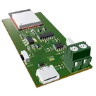
ESP32 RS485 (Modbus) Controller Module
copilot
omglab
copilot
omglab