Project Breakdown and Design

Modified project description documenting sensor integration.

15:32

Started: Modify the project description to document the RCWL-0516 integration, including OUT → GPIO13, VCC → 5V, GND → ground, and add hashtags #RCWL-0516 #MotionSensor.
Updated to: "ESP32-CAM with OV2640 and Integrated RCWL-0516 Motion Sensor Evaluation Board"

Worked

0:06

I’ve completed all steps for integrating the RCWL-0516 sensor:
Work done
  • Added RCWL-0516 with its footprint
  • Connected OUT to IO13 (net MOTION_OUT)
  • Connected VCC to 5V
  • Connected GND to GND
  • Updated project description (#RCWL-0516 #MotionSensor)
Success criteria review
  • ✅ Sensor symbol & footprint present
  • ✅ OUT → GPIO13
  • ✅ GND → ground, VCC → 5V
  • ✅ Documentation updated
Next step Review the schematic for completeness against your functional goals, then prepare for PCB layout (footprint review, stack-up configuration, and mounting solution).
how to connect pir sensor with Ai-Thinker

explicacion sobre esp32 cam
1y
@copilot how to connect pir sensor with Ai-Thinker
2y
To connect a PIR Motion Sensor to the Ai-Thinker ESP32-CAM, the connection could be established as follows:
  1. VCC: Connect the VCC pin of the PIR sensor to the 3V3 or 5V pin on the Ai-Thinker ESP32-CAM based on the voltage requirement of PIR sensor.
    • If PIR sensor requires 3.3V: Connect PIR VCC to 3V3 (P$16) or 3V3. (P$12) on the ESP32-CAM.
    • If PIR sensor requires 5V: Connect PIR VCC to 5V (P$1) on the ESP32-CAM.
  2. GND: Connect the GND pin of the PIR sensor to any of the GND pins on the ESP32-CAM, i.e., GND (P$2), GND. (P$13), or .GND (P$9).
  3. OUT: Connect the output pin of the PIR sensor (usually denoted as OUT) to any of the available GPIOs based on your program logic. For example, you could connect it to IO4 (P$8).
Your code will need to be designed to initiate the chosen GPIO as an input and read its state. An interrupt can be configured on this pin to detect the change of state, which occurs when motion is detected by the PIR sensor.
Please note that all these connections should be made according to the data flow and terminal type. You can arrange this on Flux based on the selected pins.
Also, ensure to validate the voltage levels of PIR with ESP32 CAM, higher voltage levels could potentially damage the ESP32. Please refer to the datasheets of the ESP32-CAM board and the PIR Sensor to verify voltage levels and other details.
2y
I need a PID sensor
2y
I believe there may be a misunderstanding. PID stands for Proportional-Integral-Derivative. These are usually terms associated with a type of control algorithm, not a physical sensor.
If you're referring to a type of sensor that uses PID for control, could you please be more specific? Controllers using PID are common in various systems like temperature controllers, motion controllers, chemical controllers etc.
If you're looking to implement a PID controller in your circuit using the ESP32-CAM, you would generally do this in software rather than directly on the hardware. The ESP32-CAM would connect to the relevant sensors and actuators (for example, a temperature sensor and a heater), and the PID control algorithm would be implemented in the code running on the ESP32.
Please provide more information about your specific requirements so I can help you better.
2y
Passive Infrared
2y
Understood, in your earlier message you intended to refer to a Passive Infrared (PIR) sensor.
Here's how to hook a PIR sensor to your Ai-Thinker ESP32-CAM:
  1. VCC: Connect the VCC pin of the PIR sensor to the 3V3 or 5V pin on your ESP32-CAM based on the power requirement of the PIR sensor.
  • If the PIR sensor supports 3.3V operation, you should connect the PIR:VCC to 3V3:P$16 or 3V3.:P$12
  • If the PIR sensor requires 5V, then you need to connect the PIR:VCC to 5V:P$1
  1. Ground: Connect the ground pin (GND) of your PIR sensor to a ground pin on your ESP32-CAM. You could use GND:P$2, GND.:P$13, or .GND:P$9.
  2. Output (Signal): The output pin (usually labeled as OUT) should connect to a GPIO pin on the ESP32-CAM. This pin will read the signal from the sensor. An example connection would be PIR:OUT to IO4:P$8, but the specific pin you use can depend on your code and which pins are free.
These connections should be specified in your Flux project. Remember, the connections should respect the flow of current and the types of terminals you connect.
Once this hardware setup is complete and verified, you'll need to configure the corresponding GPIO pin as an input in your code and read its state regularly or set up an interrupt to respond to state changes.
Please verify the voltage operation range of your specific PIR sensor. Connecting a PIR sensor that requires a higher voltage to your 3.3V ESP32-CAM could possibly damage your ESP32-CAM. Always refer to the datasheets to confirm power requirements and operating voltage ranges.
2y
Someone is typing...
4
explain this project.

@copilot explain this project.
2y
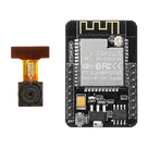
This project is centered around an ESP32 CAM module, which combines an ESP32 microcontroller with an OV2640 image sensor, making it ideal for applications involving wireless image and video transmission. The ESP32 is well-known for its Wi-Fi and Bluetooth capabilities, making this module particularly useful for IoT applications requiring remote image capture or video streaming. Ai-Thinker, the manufacturer, has designed this board to be versatile for various projects including home automation, surveillance, and any innovative projects involving image processing and remotely controlled devices.
Project Components and Connections
The project includes several I/O (Input/Output) pins and power supply pins identified by their designator names. Below is a brief overview of these components:
  • I/O Pins: These are bidirectional (bidi) terminals used for connecting to other devices, sensors, or actuators. They can be programmed to be either inputs or outputs depending on the needs of the application. Specific I/O pins mentioned are IO2, IO14, IO16, IO15, IO13, IO1/U0T, IO12, IO3/U0R, IO0, and IO4. Each pin has unique functionalities and can be used for specific tasks, such as IO1/U0T and IO3/U0R which suggest being used for serial communication (TX and RX respectively).
  • Power Pins: The project includes pins for 3.3V (3V3 and 3V3.), 5V, and Ground (GND, GND., and .GND) connections. These are essential for powering the ESP32 and its peripheral devices. The presence of both 3.3V and 5V pins indicates that the board can be powered directly from a USB connection or a compatible battery, and provides flexibility regarding the power source and voltage levels required by connected peripherals or sensors.
  • Designator Prefix: Each component is uniquely identified with a prefix (e.g., P for power pins and I/O pins), followed by a specific pin number (e.g., P$7 for IO2), which simplifies the identification and connection process in the circuit design.
Current Project Status
As per the provided description, no electrical connections have been established yet in the project. This implies the initial stage of design, where components have been placed on the schematic but are yet to be interconnected to form a working circuit.
Next Steps
  • Establishing power connections: connecting 3.3V and GND pins to the appropriate power sources.
  • Connecting I/O pins to peripherals: depending on the application, I/O pins will need to be connected to sensors, actuators, or other modules.
  • Serial connections: Utilizing IO1/U0T and IO3/U0R for serial communication, possibly with a computer or another microcontroller for data exchange.
This project offers a robust platform for developing a wide range of applications, leveraging the ESP32's capabilities alongside the OV2640 image sensor. By establishing the necessary connections and programming the ESP32, you can create a powerful system for image capture and transmission over Wi-Fi.
2y
Someone is typing...
6
New Comment

Someone is typing...
2

No files yet

Documents

    Documents are markdown text files which describe project goals, capture details, or even simulation outputs.

    Assets

    step

    ESP3-CAM v4.step

    3D3D Model
    kicad_mod

    ESP32-CAM.kicad_mod

    ESP32-CAM-FootprintFootprint
    ESP32-CAM-removebg-preview.png

    ESP32-CAM-removebg-preview.png

    ESP32-CAM-removebg-previewThumbnail

    ESP32-CAM

    ESP32-CAM thumbnail
    ESP32-CAM with OV2640 and Integrated RCWL-0516 Motion Sensor Evaluation Board

    Properties

    Development Board

    Ai-Thinker

    Ai-Thinker ESP32-CAM WiFi BT BLE

    ESP32-CAM

    Parametric

    Pricing & Availability

    Distributor

    Qty 1

    Controls