ESP8266 Schematics
The ESP8266 is a low-cost microcontroller with built-in Wi-Fi capability. It is a versatile platform that can be used in a wide range of applications, including home automation, internet of things (IoT), and wearable electronics. The ESP8266 has a powerful processor and on-board memory, making it capable of running complex programs and connecting to the internet to transmit and receive data. One of the key use cases for the ESP8266 is in home automation, where it can be used to control and monitor various devices and appliances through a network connection. It can also be used in IoT applications, where it can collect and transmit data from sensors and other devices to the cloud for analysis and storage. Flux.ai has the world's largest community-driven public library of ESP8266 MCUs, with footprints, symbols, datasheets, and simulation models. This library is an invaluable resource for engineers and developers working with the ESP8266, providing access to a wealth of information and resources to help them design and build innovative applications.
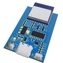
ESP-WROOM-02D Module
This project is a reference design for an ESP-WROOM-02D based device. It features USB-C for power and data transfer, onboard voltage regulation, and multiple peripheral connections. It also includes a CH340C for USB to serial conversion #referenceDesign #Module #ESP8266 #WROOM #RF #WIFI #MCU #reusable #module #simple-embedded #espressif #sublayout
12 Uses1 Stars
Nodemcu-12E ESP8266 8nww
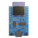
NodeMCU V3 ESP8266 ESP-12E is WiFi development board that helps you to prototype your IoT product with few Lua script lines, or through Arduino IDE. The board is based on ESP8266 ESP-12E variant, unlike other ESP-12E, you won’t need to buy a separate breakout board, usb to serial adapter, or even solder it to a PCB to get started, you will only need a usb cable (Micro USB).
0 Uses1 StarsNodemcu-12E ESP8266 vuik
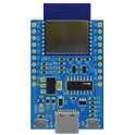
NodeMCU V3 ESP8266 ESP-12E is WiFi development board that helps you to prototype your IoT product with few Lua script lines, or through Arduino IDE. The board is based on ESP8266 ESP-12E variant, unlike other ESP-12E, you won’t need to buy a separate breakout board, usb to serial adapter, or even solder it to a PCB to get started, you will only need a usb cable (Micro USB).
0 Uses1 StarsNodemcu-12E ESP8266
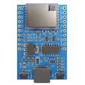
NodeMCU V3 ESP8266 ESP-12E is WiFi development board that helps you to prototype your IoT product with few Lua script lines, or through Arduino IDE. The board is based on ESP8266 ESP-12E variant, unlike other ESP-12E, you won’t need to buy a separate breakout board, usb to serial adapter, or even solder it to a PCB to get started, you will only need a usb cable (Micro USB).
0 Uses1 StarsNodemcu-12E ESP8266 Smart Light
NodeMCU V3 ESP8266 ESP-12E is WiFi development board that helps you to prototype your IoT product with few Lua script lines, or through Arduino IDE. The board is based on ESP8266 ESP-12E variant, unlike other ESP-12E, you won’t need to buy a separate breakout board, usb to serial adapter, or even solder it to a PCB to get started, you will only need a usb cable (Micro USB).
0 Uses1 Stars
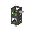
CRYPTO Real Time Tracker
CRYPTOiNK is an E-ink Display to Realtime Update Select Crypto Currency. CRYPTOiNK uses a TP4056 Charger to charge a 6000mAh Lipo Battery. Built into the Charger is a Low Voltage, Over Voltage, and Over Current Protection Circuit. Because the Ilpo battery does not provide a constant voltage and ranges from 3.4 - 4.2V, a MT3608 DC/DC Boost Module to provide a consistent Voltage for the Waveshare Driver board to regulate down to a 3.3V that is used by the ESP8266 and Eink Display. The device based on ESP8266 and supports the Thingspeak IoT server for currencies real-time communications.
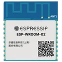
0 Uses1 StarsESP-12F
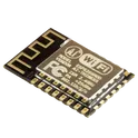
WiFi 802.11b/g/n Transceiver Module 2.4GHz ~ 2.5GHz Integrated, Trace Surface Mount The ESP-12F is a compact WiFi module based on the ESP8266EX, widely used in IoT and embedded systems due to its low cost and built-in networking capabilities. Integrated WiFi (2.4 GHz) Supports 802.11 b/g/n Built-in TCP/IP stack (no external WiFi processor needed) Microcontroller + WiFi in one Powered by the ESP8266EX SoC Can run user applications directly (not just a WiFi modem) Flash Memory Typically 4 MB SPI flash (varies by version) GPIO Support Multiple multifunction pins: Digital I/O PWM I2C SPI UART ADC (1 channel) Size: ~16 mm × 24 mm Mounting: Castellated SMD module Antenna: Built-in PCB trace antenna (requires proper keepout zone) Power Requirements Operating Voltage: 3.0V – 3.6V (typical 3.3V) Current Consumption: Idle: ~70 mA Peak (TX): up to ~300 mA Common Interfaces UART – programming and debugging SPI – peripheral communication I2C (software-based) GPIO – general-purpose control #commonpartslibrary #transceiver #module #wireless #rf #wifi
179 Uses0 StarsZAPP-LB-V1 Smart Relay Logic Board
2-layer SELV ESP8266 smart relay logic board using an ESP-12F module, MCP1700-3302E 5V-to-3.3V LDO, exact 2x7 relay/control connector pinout, 4-pin UART programming header, GPIO0 flash test point, active-low GPIO2 status LED, power and GPIO test points, 55x45 mm board outline, top-side assembly, bottom solid ground pour, ESP-12F antenna keepout, 4 M3 mounting holes, and silkscreen connector labels for production use.
0 Uses0 StarsFemale Maroon Battle Mech
Wearable health device prototype schematic with ECG sensing via AD8232, motion sensing via BNO085 or BMI270 IMU breakout, on-board processing using TI TM4C123G LaunchPad or MSPM0G3507 LaunchPad, optional ESP8266 Wi-Fi, LiPo battery charging with MCP73831, regulated 3.3 V power from TPS63031 buck-boost or AP2112 LDO prototype option, and user interfaces including electrode connector, JST battery connector, programming header, and optional on/off switch.
0 Uses0 StarsLoyal Peach Scramble Suit
Industrial dual motor controller using an ESP8266 NodeMCU and L298N dual H-bridge for 2x 12V 2A DC motors, with MQTT remote control, manual override buttons, 5-bit DIP addressing, reset input, status LEDs, SS34 reverse-polarity protection, 5A fuse, LM2596 5V buck conversion, TVS surge protection, and future expansion provisions for INA219 current sensing, OTA firmware, RS485, and enclosure integration.
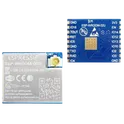
0 Uses0 StarsESP-WROOM-02 Reference Design
This project is a reference design for an ESP-WROOM-02 based device. It features USB-C for power and data transfer, onboard voltage regulation, and multiple peripheral connections. It also includes a CH340C for USB to serial conversion #referenceDesign #project #ESP8266 #WROOM #RF #WIFI #MCU #referenceDesign #simple-embedded #espressif #template #reference-design #polygon
0 Uses0 StarsESP-WROOM-02D Reference Design
This project is a reference design for an ESP-WROOM-02D based device. It features USB-C for power and data transfer, onboard voltage regulation, and multiple peripheral connections. It also includes a CH340C for USB to serial conversion #referenceDesign #project #ESP8266 #WROOM #RF #WIFI #MCU #referenceDesign #simple-embedded #espressif #template #reference-design
0 Uses0 StarsESP-WROOM-02U Reference Design
This project is a reference design for an ESP-WROOM-02U based device. It features USB-C for power and data transfer, onboard voltage regulation, and multiple peripheral connections. It also includes a CH340C for USB to serial conversion #referenceDesign #project #ESP8266 #WROOM #RF #WIFI #MCU #referenceDesign #simple-embedded #espressif #template #reference-design #polygon
0 Uses0 Stars