Arduino Schematics
Arduino is an open-source electronics platform based on easy-to-use hardware and software. It is designed for anyone to use, regardless of their level of expertise in electronics. Arduino boards are commonly used for a wide range of projects, including building DIY devices, controlling home appliances, creating interactive art installations, and more. One of the key benefits of Arduino is its community-driven nature. There are a plethora of resources available online for those looking to learn more about Arduino or troubleshoot problems they may encounter while working on a project. Flux.ai has the world's largest community-driven public library of Arduino footprints, symbols, datasheets, and simulation models. This makes it an invaluable resource for those looking to take their Arduino projects to the next level. Whether you're a beginner or a seasoned pro, Flux.ai has something to offer.
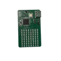
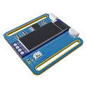
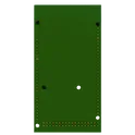
8x8 Display with IMU V2
Mixed Voltage Arduino Nano Integration Example on a 4 Layer PCB Changelog/TODO: -Breakout the SPI Bus in a 2.54mm header in a snap off manner -add an IMU -Reorder the rows of the LEDs Tutorials: https://circuitdigest.com/microcontroller-projects/interfacing-max7219-led-dot-matrix-display-with-arduino
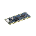
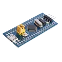
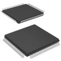
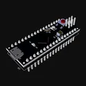
0 Uses6 StarsArduino Nano Barebones - SMD
Important Note: You must connect your own SPI/ICSP programming header if you want to burn the Arduino bootloader to the MCU. SMD Manufacturing: Need a hotplate and solderpaste Good to haves: - Oscillator Decoupling Caps Expose UART via connector Programming Button Onboard LED Reset Button You don't have to populate everything! Only these are mandatory: Reset Button Find the reference schematic here: https://www.arduino.cc/en/uploads/Main/ArduinoNano30Schematic.pdf
1.8k Uses6 Stars-cf6ba8ec-6d5b-6027-b261-91c0e3e778e6.svg)
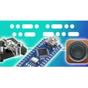
An Arduino-based Device for visually impaired people
A special wearable device based on the Arduino board. Which can be worn on a cloth by using a strip for blinds. The device is equipped with an ultrasonic sensor, motor, and buzzer. Basic working: When the ultrasonic sensor detects obstacle the device will notify the user through vibrations and sound beeps. The intensity of vibration and rate of beeping increases with decrease in distance and this is a fully automated device. Powering the modules - Connect the 4 Arduino pro mini to a USB male pin and connect to a power bank. For the module in the hand use a small lithium battery. Multiple devices can be placed on person's body as follow: two for both shoulder, another two for both knees and one for the hand. Using the five ultrasonic sensors, blind people can detect the objects in a five dimensional view around them and can easily travel anywhere.
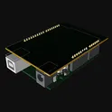
5 Uses6 StarsArduino Uno R3 Shield Max485 Double
Template for Arduino Uno R3 Shield. Include an official pinout so you will always know Arduino names, the alternative roles of pins, which one is SDA, or SCL, etc. On PCB you can find the 3D model of the Arduino Uno R3 itself along with the board outline on the silkscreen. #Arduino #Uno #Shield #Template #project-template #project
3.2k Uses5 Stars-59934b57-113a-1922-4834-67d18f6a5aae.svg)
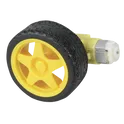
Autonomous "Follow Me" Cooler
An Arduino Uno powers this autonomous “follow me” cooler that connects to a smartphone via Bluetooth and uses GPS to navigate. The robot cooler connects to a smartphone via Bluetooth and uses GPS to navigate. All the electronics will be contained in the base so that other objects can be carried as well. The electronics were installed in the box cutout under the platform. An Arduino Uno and a 5v battery to power the sensors, Bluetooth, and control logic. A 3s LiPo battery was used to power the motors. A HC-05 Bluetooth module was mounted at the front of the platform for better range. The rest of the components including a L298N motor driver, PAM-7Q GPS, and HMC6883L compass were mounted inside and connected to the Arduino through the breadboard. The compass works with I2C, so we connected the SLC and SDA pins to A5 and A4 respectively. The rest of the pins were connected through digital I/O.
0 Uses5 StarsArduino Watch Module
This module is a minimalist Arduino Watch design. Consisting of a Microchip ATTINY85-20SU microcontroller, an OLED display for visual output, two user buttons for interface, and a Li-ion Battery for power. The schematic also includes graphic user interface with ISP for programming and minimal passive components for functionality. #wearableDevices #project #Template #projectTemplate #reusable #module #simple-embedded #microchip #arduino #sublayout
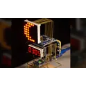
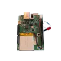
10 Uses4 StarsStrangest LED Blinker TestSite
Project Overview: This project is an enhanced LED blinking circuit that goes beyond a simple 555 timer-based design. It incorporates additional features such as random blinking patterns, speed control, and a start/stop function. The project utilizes a microcontroller, such as an Arduino or Raspberry Pi, to control the blinking patterns, speed, and start/stop functionality. LED Blinking: The board features a total of 8 LEDs that blink in various random patterns. When the board is powered on, even before user interaction, the LEDs start blinking randomly, creating an eye-catching display. Each LED has its own current-limiting resistor to ensure proper current flow and prevent damage. The microcontroller is programmed to generate random blinking patterns for the LEDs, ensuring that the LEDs do not blink in a predictable or sequential order. This random blinking adds an element of unpredictability and visual interest to the project. Speed Control: The board includes two speed control buttons that allow the user to adjust the blinking speed of the LEDs. Button 1 is designated as the "fast" button, increasing the blinking speed when pressed, while Button 2 is designated as the "slow" button, decreasing the blinking speed when pressed. The speed control provides a range of blinking speeds, from a slow, gradual blink to a rapid, strobe-like effect. The microcontroller monitors the state of the speed control buttons and adjusts the blinking speed accordingly. Start/Stop Functionality: A third button serves as a start/stop control. When pressed, it toggles the blinking of the LEDs on or off. This allows the user to freeze the blinking pattern at any desired moment or resume the blinking when desired. The microcontroller handles the start/stop functionality by turning the LEDs on or off based on the state of the start/stop button. Manual Speed Adjustment: In addition to the speed control buttons, the board includes a potentiometer or variable resistor. This component allows the user to manually adjust the blinking speed of the LEDs by turning the knob or sliding the control. The manual speed adjustment provides more precise and customizable control over the blinking speed compared to the preset speeds of the buttons. The microcontroller reads the analog value from the potentiometer and adjusts the blinking speed accordingly. Power and Connectivity: The board is powered through a USB-C or USB-micro B connector, allowing it to be easily connected to a power source such as a computer or wall adapter. A voltage regulator may be included to ensure a stable and appropriate voltage supply to the components. A power switch is incorporated to conveniently turn the board on or off.
0 Uses4 StarsNodemcu-12E ESP8266
NodeMCU V3 ESP8266 ESP-12E is WiFi development board that helps you to prototype your IoT product with few Lua script lines, or through Arduino IDE. The board is based on ESP8266 ESP-12E variant, unlike other ESP-12E, you won’t need to buy a separate breakout board, usb to serial adapter, or even solder it to a PCB to get started, you will only need a usb cable (Micro USB).
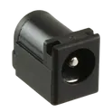
100 Uses4 StarsPJ-202A
Power Barrel Connector Jack 2.10mm ID (0.083"), 5.50mm OD (0.217") Through Hole, Right Angle The PJ-202A is a DC power jack connector (barrel jack) commonly used in electronic devices to provide a stable DC power input. It is designed for through-hole PCB mounting and supports a right-angle (horizontal) orientation, making it suitable for compact PCB layouts. This connector typically mates with a 2.0 mm center-pin DC plug and is widely used in consumer electronics, routers, embedded systems, and small power supply boards. Key Features Connector Type: DC power jack (barrel type) Center Pin Size: 2.0 mm Outer Diameter Compatibility: ~6.5 mm plug type Mounting Style: Through-hole Orientation: Right-angle / horizontal PCB mount Rated Current: up to 2.5 A Rated Voltage: up to 24 V DC ontact Configuration: 2 conductors with internal switch option Durability: ~5,000 insertion cycles Operating Temperature: -25°C to +85°C Flammability Rating: UL94V-0 plastic housing Typical Applications Embedded systems Arduino / DIY electronics power input Consumer electronics Router / modem power input Battery-powered device charging inputs DC-005 barrel jack #commonpartslibrary #connector #barrel #jack #tht
129 Uses3 Stars