Relays
A relay is an electrically operated switch that allows a low power circuit to control a high power circuit. It consists of a coil, which is activated by an electric current, and a set of contacts that open or close when the coil is activated. Relays have a wide range of use cases, including controlling the flow of electricity in a circuit, protecting electrical components from damage, and amplifying signals. They are commonly used in automotive systems, HVAC systems, and control panels. Flux.ai has the world's largest community-driven public library of relays, with footprints, symbols, datasheets, and simulation models. This library is a valuable resource for engineers and designers looking for reliable and accurate information on relays.
109RF50-1-A-5/2D
The 109RF50-1-A-5/2D is a Pickering Electronics Series 109 Micro-SIL® RF reed relay designed for high-density PCB applications requiring low-level signal switching and excellent RF performance. It features a 50 Ω coaxial configuration, SPST normally open (1 Form A) contact arrangement, and a 5 VDC coil with an integrated diode for coil suppression. The relay uses a mu-metal magnetic shield package to minimize magnetic interaction when multiple relays are closely stacked, making it suitable for compact test systems, RF switching matrices, and high-speed signal applications. Key Features Relay Type: Micro-SIL® RF Reed Relay Manufacturer: Pickering Electronics Series: Series 109 Contact Configuration: SPST-NO (1 Form A) Coil Voltage: 5 VDC Coil Resistance: 375 Ω Switching Current: Up to 0.5 A Switching Power: 10 W Maximum Switching Voltage: 200 V Standoff Voltage: 240 V Contact Type: Low-level dry reed contact RF Characteristic Impedance: 50 Ω coaxial configuration Integrated Protection: Internal diode included Package Type: Through-hole Micro-SIL (SIP) Magnetic Shielding: Mu-metal package for reduced relay interaction in dense layouts Operating Temperature: Approximately -20 °C to +85 °C High Density Mounting: Stackable on 0.15 × 0.6 inch pitch for space-saving PCB designs Typical Applications RF signal switching systems Automatic Test Equipment (ATE) switching matrices High-speed digital signal switching RF filters and instrumentation equipment Communication test platforms Precision measurement equipment #PickeringElectronics #109RF50 #ReedRelay #RFRelay #MicroSILRelay #SPSTRelay #SignalSwitching #RFSignal #ATEEquipment #TestAndMeasurement #PCBRelay #HighDensityDesign #ElectronicComponents
0 Uses0 StarsM83536/2-024M
Mid-Range Relays, 2 Form C, DPDT, 2 C/O, Coil Suppression Diode, Gold Terminal Plating, 5 A, 28 VDC Coil Voltage, CII FCB-205 Series The M83536/2-024M is a hermetically sealed electromechanical power relay built to comply with the MIL-PRF-83536 military specification family, a standard governing high-reliability relays intended for use in demanding military, aerospace, and defense electronic systems. Devices manufactured under this specification series are designed to meet stringent requirements for mechanical ruggedness, electrical performance consistency, and long-term reliability under the extreme vibration, shock, temperature cycling, and altitude conditions typically encountered in airborne, shipboard, and ground military platforms. This relay is configured as a double-pole, double-throw switching device, meaning it provides two independently switched sets of contacts that can each connect to one of two possible circuit paths, controlled by a single energized coil. This configuration is commonly used in applications requiring simultaneous switching of two separate circuits, such as redundant power path switching, dual-channel signal routing, or coordinated control of multiple subsystems from a single control signal. The relay operates on momentary, non-latching actuation, meaning the contacts return to their de-energized state as soon as coil power is removed, rather than remaining in their last-commanded position. The coil is designed for direct-current control voltage typical of military and aerospace 28-volt electrical systems, a standard power bus voltage used extensively in aircraft, military vehicles, and shipboard electrical systems. The device's flange-style mounting construction allows it to be securely fastened to a chassis or panel, providing the mechanical stability needed to maintain reliable contact performance under the sustained vibration and shock loading common in military platform environments. Internal contact construction uses a silver-cadmium-oxide contact material, chosen for its strong arc-resistance and resistance to contact welding under repeated switching of inductive or resistive loads. As a hermetically sealed device manufactured to a formal military specification, the relay undergoes rigorous qualification and lot-acceptance testing to verify long-term mechanical and electrical performance, including extended life-cycle switching tests, vibration and shock qualification, and environmental exposure testing. This makes the part suitable for use in flight-critical, mission-critical, or other high-reliability electromechanical switching applications where field failure is not an acceptable risk. The relay is supplied with through-hole solder-pin terminations for both coil and contact connections, supporting traditional through-hole assembly methods consistent with the conservative, well-proven manufacturing processes favored in military and aerospace hardware production. Spec Sheet Identification Part Number: M83536/2-024M Specification Family: MIL-PRF-83536 Manufacturer: TE Connectivity (CII) Functional Classification Device Type: Electromechanical power/signal relay Contact Configuration: Double-pole, double-throw (DPDT) Actuation Type: Momentary, non-latching Coil Input Type: DC control Electrical Characteristics Coil Voltage: Military-standard 28V DC class Coil Resistance: Moderate coil resistance class Contact Rating: Mid-range current switching class Contact Voltage Rating: Compatible with 28V DC and standard AC switching voltages Output Type: AC/DC switching capable Contact & Construction Details Contact Material: Silver-cadmium-oxide (AgCdO) Contact Form: 2 Form C (DPDT, normally open/normally closed) Sealing: Hermetically sealed construction Mounting Style: Flange mount, through-hole Environmental & Qualification Specification Compliance: MIL-PRF-83536 military relay specification Application Class: Military and aerospace electromechanical switching Export Classification: EAR99 export control classification RoHS Compliance: Yes Mechanical Specifications Termination: Solder pin, through-hole Mounting Type: Through-hole, flange-mounted Build Style: Mid-range relay form factor consistent with the M83536 family Packaging Supply Format: Individually packaged per military relay handling and ESD protection standards #M83536 #TEConnectivity #MilitaryRelay #AerospaceRelay #MILPRF83536 #DPDTRelay #ElectromechanicalRelay #HermeticallySealed #PowerRelay #SignalRelay #DefenseElectronics #AviationElectronics #FlangeMount #ThroughHole #MilAeroComponent #EngineeringSpec #ComponentLibrary #CommonPartsLibrary #RoHSCompliant #HighReliabilityRelay
0 Uses0 StarsTPS48100QDGXRQ1
High-Side Gate Driver IC Non-Inverting 19-VSSOP The TPS48100QDGXRQ1 is an automotive-grade dual high-side gate driver integrated circuit manufactured by Texas Instruments. It is designed to drive external N-channel power MOSFETs configured as high-side switches, providing the gate-drive voltage and current needed to turn the switches fully on and off with controlled timing. The device targets automotive and other harsh-environment power switching applications where a robust, low quiescent current solution is needed to control loads such as motors, relays, solenoids, lighting, and other inductive or resistive loads powered from a vehicle battery rail. As a member of TI's automotive low-IQ high-side driver portfolio, the device is built to tolerate the wide voltage swings and transient conditions characteristic of automotive electrical systems, including load dump events and cold-crank voltage sags, while maintaining very low standby current draw when the driven loads are not active. This low quiescent current characteristic is particularly valuable in always-on automotive modules, where minimizing parasitic battery drain during vehicle-off states is a key design requirement. The device's two independent driver channels operate synchronously, allowing coordinated control of dual high-side switches from a shared set of control and protection circuitry, which is useful in applications such as dual-channel load switching, H-bridge-adjacent driver stages, or redundant power path control. The non-inverting input structure means that the gate driver outputs follow the logic state of the input control signals directly, simplifying integration with microcontroller-based control logic without requiring additional inverting stages. Internally, the device manages the charge pump or bootstrap circuitry needed to generate a gate voltage above the battery rail, which is necessary to fully enhance an N-channel MOSFET configured in the high-side position. This internal voltage generation simplifies the external bill of materials compared to discrete charge-pump driver implementations. The device is qualified to automotive electronics reliability standards, reflecting the rigorous stress testing and quality requirements expected of components used in vehicle electrical and powertrain-adjacent systems. It is housed in a small-outline surface-mount package suited to space-constrained automotive control module designs, and it is supplied in tape-and-reel or cut-tape packaging formats to support both high-volume automated assembly and lower-volume prototyping needs. Spec Sheet Identification Part Number: TPS48100QDGXRQ1 Device Family: TPS48100-Q1 Manufacturer: Texas Instruments Functional Classification Device Type: Dual high-side gate driver IC Driven Configuration: High-side Channel Type: Synchronous, dual independent drive channels Gate Type Driven: N-channel power MOSFET Input Logic: Non-inverting Electrical Characteristics Supply Voltage Range: Wide automotive-class supply range Quiescent Current: Low-IQ class, optimized for always-on automotive modules Output Drive Current: Symmetric source and sink peak output current Internal Gate Drive Generation: Integrated charge pump/bootstrap-style high-side gate drive generation Protection & Diagnostics Application Context: Suited for protected high-side switching designs typical of the automotive driver family Robustness: Designed to tolerate automotive transient and load-dump conditions Environmental & Qualification Temperature Grade: Extended automotive operating temperature range Automotive Qualification: AEC-Q100 qualified RoHS Compliance: Yes Package Package Type: Small-outline surface-mount package, VSSOP style Mounting: Surface mount technology (SMT) Packaging Format Supply Format: Tape-and-reel, cut-tape, or reel-on-demand packaging options #TPS48100 #TexasInstruments #GateDriver #HighSideDriver #AutomotiveIC #AECQ100 #PowerManagement #MOSFETDriver #LowIQ #VSSOP #SurfaceMount #AutomotiveElectronics #PowerSwitching #SemiconductorIC #EngineeringSpec #ComponentLibrary #CommonPartsLibrary #RoHSCompliant #VehicleElectronics #PCBDesign
21 Uses0 StarsCPC1709J
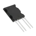
IXYS Integrated Circuits brings OptoMOS® technology, reliability and compact size to a new family of high-power Solid State Relays. As part of this family, the CPC1709J single-pole normally open (1-Form-A) DC Solid State Power Relay employs optically coupled MOSFET technology to provide 2500Vrms of input to output isolation. The output, constructed with an efficient MOSFET switch and photovoltaic die, uses IXYS Integrated Circuits’ patented OptoMOS architecture while the input, a highly efficient infrared LED, provides the optically coupled control. The combination of low on-resistance and high load current handling capability makes this relay suitable for a variety of high performance DC switching applications. The unique ISOPLUS-264 package pioneered by IXYS enables Solid State Relays to achieve the highest load current and power ratings. This package features a unique IXYS process where the silicon chips are soft soldered onto the Direct Copper Bond (DCB) substrate instead of the traditional copper leadframe. The DCB ceramic, the same substrate used in high power modules, not only provides 2500Vrms isolation but also very low junction-to-case thermal impedance (0.3 °C/W). Features • 22.8ADC Load Current with 5°C/W Heat Sink • Low 0.05 On-Resistance • 60VP Blocking Voltage • 2500Vrms Input/Output Isolation • Low Thermal Impedance: JC = 0.3 °C/W • Isolated, Low Thermal Impedance Ceramic Pad for Heat Sink Applications • Low Drive Power Requirements • No EMI/RFI Generation Applications • Industrial Controls / Motor Control • Robotics • Medical Equipment—Patient/Equipment Isolation • Instrumentation • Multiplexers • Data Acquisition • Electronic Switching • I/O Subsystems • Meters (Watt-Hour, Water, Gas) • Transportation Equipment #CPC1709J #IXYS #Littelfuse #SolidStateRelay #SSR #OptoMOS #PowerRelay #DCRelay #MOSFETRelay #HighCurrentSwitching #ElectricalIsolation #IndustrialElectronics #PowerManagement #BatterySystems #AutomationControl
24 Uses0 StarsL9961TR
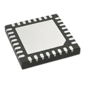
Battery Multi-Function Controller IC Lithium Ion/Polymer 32-VFQFPN (5x5) L9961 is part of a complete battery pack monitoring, balancing, and protecting system for Li-Ion and Li-Polymer cells in 3, 4 or 5 series configurations. The L9961 uses a high precision ADC to provide cell voltage, stack voltage and temperature conversion via external NTC. Voltage monitoring functions are cyclically performed with a programmable loop time. Stack current is also monitored via a high accuracy CSA, continuously running and performing also Coulomb counting. Cell balancing is available and can be simultaneously activated on all cells. IC configuration and information exchange for SOC/SOH estimation are performed via I2C peripheral. The IC also integrates a dual pre-driver programmable in both HS/LS configurations for driving pack relays. L9961 also implements battery pack fuse protection to prevent fire and explosion hazards. A 3.3 V regulator with a high current capability is available for supplying pack controller and other external circuitry in both standby and normal operation modes. The IC protects the battery pack against over/under voltage conditions and monitors for over/ under temperature. It also features protection against overcurrent (both directions) and short-circuit in discharge events. Safety-relevant configurations can be stored in the internal NVM to avoid re-programming the device at each wake-up. Features • 2 μA shipment - DEEP SLEEP mode current and 5 μA standby consumption (with VREG LDO active) standby consumption (with VREG LDO active) • Integrated 3.3 V VREG LDO for supplying MCU and LEDs • Measures cell voltage (3 to 5 cells), with over/undervoltage detection and balance undervoltage protection • 12-bit voltage measurement with maximum error of ±15 mV in the [1.5 – 4.5] V range, for -40 °C < TJ < 105 °C • Measures stack voltage, with over/under voltage detection and plausibility check vs. sum of cells • Measures pack temperature via NTC, with over/undertemperature detection • Ratiometric temperature measurement with ±0.8% max. gain error in the [0.2 – VREG] V range, for -40 °C < TJ < 105 °C • Measures battery current, with Coulomb counting, overcurrent (both directions) and short-circuit in discharge protection. • 16-bit signed current measurement with 0.1% full scale error at room temperature • I 2C peripheral for device programming and data transfers over I2C bus • Cell balancing supporting up to 70 mA per cell • Dual configurable HS/LS predriver for pack relay management • Pack fuse management • Embedded NVM for configuration parameters storage • High hotplug robustness Applications • Cordless power tools • Backup energy storage systems and UPS • Light electric vehicles (e-bikes, scooters, etc.) • Portable and semi-portable equipment • Medical equipment #L9961TR #BatteryManagement #BMS #LiIonBattery #LiPoBattery #STMicroelectronics #BatteryProtection #CellBalancing #CoulombCounting #PowerManagement #EmbeddedSystems #EnergyStorage #EBike #PowerTools #ElectronicsDesign
6 Uses0 StarsTPSI3100QDVXRQ1
1.5A, 2.5A Gate Driver Magnetic Coupling 5000Vrms 2 Channel 16-SSOP # TPSI3100QDVXRQ1 ## General Description The TPSI3100QDVXRQ1 is an automotive-qualified isolated switch driver manufactured by Texas Instruments and specifically designed for driving solid-state relay architectures based on silicon carbide and gallium nitride power devices. The device integrates an isolated power supply and gate-driver functionality into a compact solution, eliminating the need for external isolated bias supplies in many applications. Its advanced architecture enables reliable control of high-voltage switching systems while providing reinforced isolation, fast switching performance, and enhanced system efficiency. The component is optimized for automotive, industrial automation, energy storage, renewable energy, electric vehicle infrastructure, and high-voltage power conversion applications requiring robust isolation and dependable switching control. ## Key Features ### Isolation Architecture * Integrated isolated switch driver solution * Reinforced isolation technology * High-voltage system compatibility * Enhanced safety and system protection * Reliable signal transfer across isolation barriers * Reduced external component requirements ### Driver Characteristics * Optimized gate-drive functionality * Fast switching performance * Efficient control of solid-state switching devices * Stable drive capability * Low-power control operation * High reliability switching support ### Power Management Features * Integrated isolated power supply * Simplified system architecture * Reduced design complexity * Improved power conversion efficiency * Lower overall component count * Optimized power consumption ### Protection Features * Enhanced electrical isolation * Improved system safety * Reliable operation in high-voltage environments * Robust transient immunity * Stable operation during fault conditions * Protection against electrical stress ### Electrical Characteristics * High-speed switching capability * Low standby power requirements * Reliable signal integrity * Stable operation across operating conditions * Suitable for demanding power electronics applications ### Package Characteristics * Compact surface-mount package * High-density PCB layout support * Automated assembly compatible * Industrial and automotive system integration * Space-efficient implementation ### Material Construction * Advanced semiconductor technology * Automotive-grade manufacturing quality * RoHS-compliant materials * Lead-free package construction * High-reliability integrated circuit architecture ### Environmental Characteristics * Automotive-qualified reliability * Suitable for harsh operating environments * Long operational service life * Stable thermal performance * Reliable continuous-duty operation ### Application Areas * Solid-State Relays * Automotive Electronics * Electric Vehicle Systems * Battery Energy Storage Systems * Renewable Energy Equipment * Industrial Automation Systems * High-Voltage Power Conversion * Motor Drive Systems * Charging Infrastructure * Power Distribution Equipment * Industrial Power Supplies * Advanced Power Electronics ### Compliance * Automotive Qualified * RoHS Compliant * Lead-Free Compatible * Industrial and Automotive Grade Isolated Driver Solution ## Manufacturer Texas Instruments ## Product Family TPSI Isolated Switch Driver Series #TPSI3100QDVXRQ1 #TexasInstruments #IsolatedDriver #SolidStateRelay #GateDriver #AutomotiveElectronics #PowerElectronics #SiliconCarbide #GalliumNitride #IndustrialAutomation #EnergyStorage #ElectricVehicles #PowerConversion #EmbeddedSystems #ElectronicsEngineering
0 Uses0 Stars1726202
8 Position Wire to Board Terminal Block Horizontal with Board 0.200" (5.08mm) Through Hole ## Engineering Specification ## General Description The **1726202** is a Phoenix Contact **MKKDSN series PCB terminal block** designed for compact and reliable wire-to-board connection in printed circuit board assemblies. It is intended for applications that require secure field wiring, serviceable conductor termination, and stable electrical connection between external wiring and PCB circuitry. The component is suitable for industrial control systems, automation equipment, power interfaces, instrumentation, building controls, and general electronic hardware assemblies. ## Device Identification Manufacturer Part Number: **1726202** Manufacturer: **Phoenix Contact** Product Name: **MKKDSN 1,5/ 8-5,08** Product Family: **MKKDSN 1,5** Product Line: **COMBICON Terminals** Device Category: **Connector and Interconnect Component** Device Type: **PCB Terminal Block** Connection Type: **Wire-to-Board Terminal Block** Termination Method: **Screw Connection with Tension Sleeve** Mounting Type: **Through-Hole PCB Mount** ## Functional Description The device functions as a fixed printed circuit board terminal block that allows external conductors to be connected directly to PCB circuits. The screw-clamp connection secures the conductor mechanically while maintaining electrical continuity through the terminal body and solder pins. This makes the component suitable for wiring interfaces that require durability, accessibility, and field-service capability. ## Mechanical Description The terminal block uses a compact green housing with a two-row terminal arrangement and side-access conductor entry. Its layout supports dense wiring connection on a printed circuit board while maintaining practical access for conductor insertion and screw tightening. The through-hole solder pins provide mechanical stability and electrical connection to the host PCB. ## Electrical Description The component is intended for low-voltage power and signal connection applications within the manufacturer’s specified current and voltage ratings. It supports conductor connection for typical industrial and control wiring requirements when used with compatible wire sizes, correct strip length, and proper tightening torque. ## Material and Contact Description The terminal block uses an insulating housing with internal conductive contact elements designed to transfer current from the inserted conductor to the PCB solder connection. The screw connection with tension sleeve helps maintain stable contact pressure and reliable conductor retention during normal operating conditions. ## Mounting and Assembly Description The **1726202** is intended for through-hole PCB soldering, including wave-solder assembly processes. The PCB layout should follow the manufacturer’s recommended hole size, pad pattern, spacing, and soldering guidelines. The component should be positioned to allow safe conductor insertion, screwdriver access, and adequate clearance from nearby parts or enclosure walls. ## Application Suitability The device is suitable for industrial control boards, automation modules, relay boards, power supply interfaces, building automation equipment, instrumentation systems, sensor wiring interfaces, signal distribution boards, and other electronic products requiring secure PCB wire termination. ## Design Considerations The design should account for conductor size compatibility, current carrying requirement, voltage rating, creepage and clearance spacing, tightening torque, solder joint strength, wire routing, and user access during installation or maintenance. The terminal block should not be used beyond the manufacturer’s specified electrical, thermal, or mechanical limits. ## Hashtags #commonpartslibrary #terminalblock #pcbterminalblock #phoenixcontact #mkkdsn #mkkdsnterminalblock #combicon #wiretoboard #screwterminal #fixedterminalblock #throughholecomponent #wavesoldering #soldermount #connector #interconnect #fieldwiring #industrialelectronics #automationequipment #controlsystems #powerinterface #pcbdesign #hardwaredesign #electronicscomponents #electronicparts #engineeringparts #componentlibrary #electronicsengineering
19 Uses0 Stars1726040
2 Position Wire to Board Terminal Block Horizontal with Board 0.200" (5.08mm) Through Hole ## Engineering Specification ## General Description The **1726040** is a Phoenix Contact **MKKDSN series PCB terminal block** designed for wire-to-board electrical connections in printed circuit board assemblies. It is used to provide a secure screw-clamp interface between external wiring and PCB circuitry. The component is suitable for control systems, industrial electronics, power distribution circuits, automation equipment, and general electronic assemblies requiring reliable field wiring termination. ## Device Identification Manufacturer Part Number: **1726040** Manufacturer: **Phoenix Contact** Product Series: **MKKDSN** Device Category: **Connector and Interconnect Component** Device Type: **PCB Terminal Block** Connection Type: **Wire-to-Board Terminal Block** Mounting Type: **Through-Hole PCB Mount** Termination Method: **Screw Connection** ## Functional Description The device functions as a fixed printed circuit board terminal block that allows external conductors to be connected directly to a PCB. The screw-clamp mechanism secures the wire mechanically and electrically, providing a stable connection for signal or power circuits. The terminal block is intended for applications where field wiring must be removable, serviceable, and mechanically secure. ## Mechanical Description The component uses a compact green housing suitable for PCB-mounted assemblies. It is designed for side-entry conductor connection and horizontal board installation. The terminal block construction supports organized wire routing and convenient access for installation, maintenance, and service work. ## Electrical Description The terminal block is intended for low-voltage power and signal applications within the manufacturer’s specified current and voltage ratings. It provides reliable conductor contact when properly installed with compatible wire sizes and appropriate tightening torque. ## Material and Contact Description The connector housing is typically made from insulating material suitable for electrical safety and PCB assembly use. The internal conductive elements provide the electrical path between the inserted wire and the soldered PCB connection. Proper conductor preparation and screw tightening are required to maintain stable electrical performance. ## Mounting and Assembly Description The component is intended for through-hole solder mounting on a printed circuit board. Proper PCB hole sizing, pad layout, soldering process control, and mechanical clearance should be followed according to the manufacturer’s recommended design and assembly guidance. The terminal block should be mounted in a position that allows safe wire insertion and screw access. ## Application Suitability The **1726040** is suitable for industrial control boards, automation equipment, interface modules, power supply circuits, instrumentation, building control systems, relay boards, sensor wiring interfaces, and other electronic products requiring secure PCB wire termination. ## Design Considerations The design should account for wire gauge compatibility, current rating, voltage rating, tightening torque, creepage and clearance requirements, solder joint strength, and accessibility for field wiring. The terminal block should not be used beyond the manufacturer’s specified electrical, thermal, and mechanical limits. ## Hashtags #commonpartslibrary #terminalblock #pcbterminalblock #phoenixcontact #mkkdsn #wiretoboard #connector #interconnect #fixedterminalblock #screwterminal #throughholecomponent #pcbmount #industrialelectronics #automationequipment #controlsystems #powerdistribution #fieldwiring #electronicscomponents #electronicparts #hardwaredesign #pcbdesign #engineeringparts #componentlibrary #electronicsengineering
79 Uses0 StarsIRLML6244TRPBF
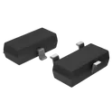
MOSFET N-CH 20V 6.3A SOT-23 The IRLML6244TRPBF is an N-channel enhancement-mode power MOSFET from Infineon Technologies (originally International Rectifier HEXFET series). It is designed for low-voltage power switching applications such as load switching, DC-DC converters, and LED control. It comes in a compact SOT-23 (Micro3™) surface-mount package, making it suitable for space-constrained PCB designs while still handling relatively high current for its size. Key Features Drain-Source Voltage (VDS): 20 V Continuous Drain Current: up to ~6.3 A (at 25°C) Very low RDS(on): ~21 mΩ @ VGS = 4.5 V ~27 mΩ @ VGS = 2.5 V Low gate threshold voltage (~0.5–1.1 V typical range) (note: not a switching guarantee) Gate-to-source voltage rating: ±12 V Low power loss due to low on-resistance High efficiency switching for low-voltage systems Power dissipation: ~1.3 W (thermal limited in SOT-23 package) Fast switching performance (low gate charge ~8.9 nC) Operating temperature range: −55°C to +150°C RoHS compliant (lead-free, halogen-free) Typical Applications Low-side load switching (MCUs, GPIO control) LED strip / RGB LED drivers Battery-powered systems DC-DC converter switching Small motor or relay driving General-purpose power management in compact electronics Important Design Note Even though it has a low VGS(th), this MOSFET is not selected based on threshold voltage. What matters is the RDS(on) at your gate drive voltage (2.5 V / 3.3 V / 5 V) to ensure it fully turns on with minimal heating. #CommonPartsLibrary #Transistor #FET #IRLML6244 #MOSFET #NChannelMOSFET #PowerElectronics #SOT23 #Infineon #HEXFET #LEDDriver #LowSideSwitch #ElectronicsComponents
282 Uses0 Stars