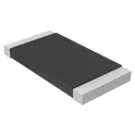
Resistors
A resistor is an electronic component that reduces the flow of current in a circuit. It is used to limit the amount of current flowing through a circuit, or to create a voltage drop in a circuit. One of the main uses of resistors is to protect components from too much current, which can cause damage or failure. Flux.ai is the world's largest community-driven public library of resistors, with footprints, symbols, datasheets, and simulation models. Whether you're an engineer working on a new design, or a student learning about electronics, Flux.ai is the go-to resource for all things resistor-related. With a wealth of information and resources available, you'll find everything you need to know about resistors, and more.
DRV8262QDDWRQ1
Bipolar Motor Driver NMOS On/Off, PWM 44-HTSSOP The DRV8262QDDWRQ1 is an automotive-qualified, high-power H-bridge motor driver from Texas Instruments designed for 24 V and 48 V automotive systems. It integrates two H-bridges capable of driving one or two brushed DC motors, a bipolar stepper motor, or thermoelectric coolers (TECs). The device features integrated high-side current sensing, programmable current regulation, and comprehensive protection functions, eliminating the need for external current-sense resistors while reducing PCB area and system cost. It supports wide supply voltages from 4.5 V to 60 V, making it suitable for demanding automotive body electronics and industrial motor control applications. Key Features Automotive AEC-Q100 Grade 1 qualified (-40°C to +125°C) Wide 4.5 V to 60 V operating supply voltage Dual H-bridge or single high-current H-bridge operation Drives: One or two brushed DC motors One bipolar stepper motor One or two thermoelectric coolers (TECs) Up to 8 A peak (dual H-bridge mode) Up to 16 A peak (single H-bridge mode) Low MOSFET on-resistance: 100 mΩ (dual H-bridge) 50 mΩ (single H-bridge) Integrated high-side current sensing with ±4% accuracy Programmable current regulation and current limiting Supports 1.8 V, 3.3 V, and 5 V logic interfaces Configurable PWM control modes (PH/EN or IN/IN) Ultra-low 3 µA sleep current Integrated protection features: Undervoltage Lockout (UVLO) Charge Pump Undervoltage (CPUV) Overcurrent Protection (OCP) Thermal Shutdown (OTSD) Fault output (nFAULT) Functional safety-capable with supporting documentation for automotive system design. #DRV8262QDDWRQ1 #MotorDriver #HBridge #AutomotiveElectronics #BrushedDCMotor #StepperMotor #CurrentSense #AECQ100 #TexasInstruments #EmbeddedSystems #PowerManagement #PCBDesign
40 Uses0 StarsCRM2512-FX-1R00ELF
1 Ohms ±1% 2W Chip Resistor 2512 (6332 Metric) Current Sense Thick Film The CRM2512-FX-1R00ELF specification defines the engineering requirements for a surface-mount current sense resistor designed for precision current measurement and power management applications. This specification establishes the functional, electrical, mechanical, thermal, environmental, and quality requirements necessary to ensure accurate resistance performance, efficient power dissipation, and long-term operational reliability in electronic systems. The component is intended for use in power supplies, battery management systems, motor control circuits, industrial automation equipment, and embedded electronic applications requiring precise current monitoring. The resistor provides a low-resistance element for current sensing while maintaining high measurement accuracy, thermal stability, and compatibility with automated surface-mount manufacturing processes. Engineering Requirements The resistor shall be manufactured using high-quality resistive materials and controlled fabrication processes to ensure stable resistance characteristics, low temperature coefficient, and reliable long-term performance. The construction shall provide consistent electrical behavior throughout the specified operating conditions without significant drift or degradation. Electrical characteristics shall ensure accurate resistance value, stable current sensing performance, and low inductance suitable for high-frequency switching environments. The component shall maintain its specified tolerance and thermal performance under continuous rated power and transient load conditions. Thermal performance shall support efficient heat dissipation through the package structure and printed circuit board interface. The resistor shall withstand normal solder reflow processes and maintain structural integrity during thermal cycling, vibration, and mechanical handling. Mechanical construction shall be compatible with standard surface-mount assembly processes and shall provide reliable solder joint formation. Workmanship shall be free from defects including cracks, delamination, contamination, plating irregularities, or structural inconsistencies that could adversely affect electrical or mechanical performance. Inspection, validation, and testing shall be conducted using calibrated equipment and controlled quality procedures to verify compliance with all applicable engineering and manufacturing requirements. Any deviation from this specification shall require formal engineering evaluation, documented technical justification, and approval through the established engineering change control process. Documentation Supporting documentation shall include engineering drawings, electrical performance specifications, thermal characterization data, qualification reports, inspection records, material declarations, and revision-controlled manufacturing documentation. All documentation shall be maintained under formal configuration management and quality assurance systems to ensure complete product traceability. Revision Control Any modification to this specification shall be managed through the formal engineering change management process. All revisions shall undergo technical review, validation, and approval before implementation to ensure continued compliance with design intent and applicable engineering standards. #EngineeringSpecification #CurrentSenseResistor #PowerElectronics #SurfaceMount #PrecisionResistor #IndustrialElectronics #PowerManagement #QualityAssurance #EngineeringDocumentation #ElectronicComponents
0 Uses0 StarsCSS4J-4026R-1L00F
1 mOhms ±1% 4W Chip Resistor Nonstandard Automotive AEC-Q200, Current Sense Metal Element Bourns Inc. CSS4J-4026R-1L00F is a high-power surface-mount current sense resistor designed for accurate current measurement in power electronics applications. It belongs to the CSS4J-4026 series and uses a metal element construction that provides low resistance, high power handling, and excellent stability for automotive and industrial applications. This device features a 1 mΩ resistance value, ±1% tolerance, and 4 W power rating, making it suitable for monitoring high-current paths while minimizing measurement losses. It is also qualified for AEC-Q200 automotive applications and operates across a wide temperature range. Key Features Component Type: SMD Current Sense Resistor (Metal Element / Metal Strip) Resistance Value: 1 mΩ (0.001 Ω) Resistance Tolerance: ±1% Power Rating: 4 W Package Size: 4026 (approx. 10.06 mm × 6.60 mm) Number of Terminals: 4 terminals (Kelvin sensing configuration) Temperature Coefficient: approximately ±75 ppm/°C Operating Temperature Range: −55°C to +170°C Construction: Metal element current shunt resistor for accurate current measurement Qualification: Automotive AEC-Q200 compliant Typical Applications Battery Management Systems (BMS) EV and automotive power systems Motor control circuits Power supplies and DC/DC converters Overcurrent monitoring and protection circuits Industrial power monitoring equipment #CommonPartsLibrary #Bourns #CSS4J4026 #CurrentSenseResistor #ShuntResistor #MetalElementResistor #AECQ200 #PowerElectronics #BatteryManagementSystem #EVElectronics #SMTComponents #PCBDesign
16 Uses0 StarsCSS4J-4026R-L500F
0.5 mOhms ±1% 5W Chip Resistor Nonstandard Automotive AEC-Q200, Current Sense Metal Element # Engineering Specification ## Product Name CSS4J-4026R-L500F ## General Description CSS4J-4026R-L500F is a precision four-terminal Kelvin current sense shunt resistor designed for accurate current measurement in high-performance electronic and power management systems. The device is intended for use in applications requiring low resistance sensing, high measurement accuracy, and stable thermal performance under varying electrical loads. The component utilizes a metal element resistive structure optimized for minimal resistance drift, reduced temperature effects, and consistent long-term stability. Its four-terminal Kelvin configuration separates current flow and voltage sensing paths, enabling improved measurement accuracy by eliminating errors caused by PCB trace and connection resistance. The device is widely used in power conversion systems, battery monitoring systems, motor control circuits, and industrial power electronics where precise current feedback is essential for control, protection, and monitoring functions. Its surface-mount construction supports compact PCB layouts and automated assembly processes while maintaining robust mechanical and electrical reliability. The design emphasizes efficient heat dissipation, stable electrical characteristics, and compatibility with demanding industrial and automotive environments. It is suitable for integration into systems requiring continuous current monitoring and high measurement fidelity. ## Functional Requirements ### Current Measurement The device shall provide accurate current sensing through a low-resistance conductive path designed for minimal measurement error. ### Kelvin Sensing Operation The device shall support four-terminal Kelvin sensing to improve measurement accuracy by separating current and voltage sensing paths. ### Signal Stability The device shall maintain stable sensing characteristics under varying load and thermal conditions. ### System Integration The component shall support integration into power electronics and embedded control systems requiring precise current feedback. ## Electrical Requirements ### Low Resistance Operation The device shall exhibit very low resistance to minimize power loss and maintain measurement accuracy. ### Thermal Stability The resistor shall maintain consistent electrical behavior under elevated operating temperatures and thermal cycling conditions. ### Power Handling The device shall support operation in high-current environments typical of power conversion and motor control systems. ### Measurement Accuracy The design shall support precise voltage drop measurement proportional to current flow for control and monitoring applications. ## Mechanical Requirements ### Surface Mount Construction The device shall be provided in a surface mount package suitable for automated PCB assembly. ### Structural Integrity The component shall maintain mechanical stability during assembly, operation, and thermal cycling. ### PCB Integration The device shall support direct integration into multilayer printed circuit board designs with optimized current path layout. ## Environmental Requirements ### Operating Conditions The device shall operate reliably under industrial and automotive environmental conditions. ### Thermal Performance The component shall maintain performance stability under continuous electrical loading and heat generation. ### Storage and Handling The device shall maintain physical and electrical integrity during storage, transport, and handling procedures. ## Quality Requirements ### Reliability The device shall provide long-term stability in resistance value and sensing accuracy under continuous operation. ### Verification Electrical, thermal, and mechanical characteristics shall be validated through appropriate testing and qualification procedures. ### Compliance The product shall conform to applicable standards for current sensing resistors used in industrial and automotive electronics. ## Documentation Requirements Technical documentation shall include application guidelines, layout recommendations for Kelvin sensing, thermal considerations, electrical characteristics, and integration practices for power electronics systems. ## Classification Tags #CSS4J4026RL500F #CurrentSenseResistor #ShuntResistor #KelvinSensing #FourTerminalResistor #PowerElectronics #BatteryManagement #MotorControl #PowerSupplyDesign #AnalogSensing #ElectricalEngineering #PCBDesign #EmbeddedSystems #IndustrialElectronics #AutomotiveElectronics #CommonPartsLibrary #ComponentLibrary #EngineeringSpecification #TechnicalDocumentation #HighCurrentSensing #PrecisionMeasurement #CircuitDesign
93 Uses0 StarsTPS259540DSGT
All details fully confirmed from Texas Instruments' official datasheet, DigiKey, and multiple verified distributor sources. Here's the complete spec. Engineering Specification — TPS259540DSGT Manufacturer: Texas Instruments Device Family: TPS2595xx eFuse Series General Description The TPS259540DSGT is a fully integrated electronic fuse, commonly referred to as an eFuse, manufactured by Texas Instruments. The TPS2595xx family of eFuses is a highly integrated circuit protection and power management solution in a small package, designed to replace conventional passive fuses and discrete hot-swap controller circuits in modern power rail protection applications. Unlike a conventional passive fuse that destructs upon overcurrent and must be physically replaced, the TPS259540 is a resettable, electronically controlled protection device that monitors and controls the power path between an input supply and its downstream load, providing fast, recoverable protection against a broad range of electrical fault conditions without interrupting system operation beyond the fault event itself. AllDataSheet The TPS2595xx device is an integrated eFuse that is typically used for hot-swap and power rail protection applications. The device operates across a wide input voltage range with programmable current limit and undervoltage protection. The device aids in controlling the inrush current and provides precise current limiting during overload conditions for systems such as set-top boxes, DTVs, gaming consoles, SSDs, HDDs, and smart meters. The device also provides robust protection for multiple faults on the sub-system rail. Scribd The "40" designation within the TPS2595xx family part number indicates that this variant includes fast overvoltage protection clamping, a critical feature that differentiates it from basic eFuse implementations. Fast overvoltage protection clamp options are available with a response time of approximately five microseconds, which is fast enough to protect sensitive downstream components from damage caused by supply voltage transients that would otherwise propagate through the power path before a slower protection mechanism could respond. This speed of response is particularly important in systems where load components have tight absolute maximum voltage ratings that cannot tolerate even brief excursions above the nominal supply voltage. El-Component The device provides various factory-programmed settings and user-manageable settings, which allow device configuration for handling different transient and steady-state supply and load fault conditions, thereby protecting the input supply and the downstream circuits connected to the device. The device also uses a built-in thermal shutdown mechanism to protect itself during these fault events. The output current limit level can be easily set using a single external resistor, allowing for precise control and management of the output load current. Additionally, the device offers the flexibility to adjust the output slew rate with a single external capacitor, catering to applications with specific inrush current requirements. ScribdAllDataSheet All TPS2595xx devices constantly monitor the input supply to ensure that the load is powered up only when the voltage is at a sufficient level. During the start-up condition, the device waits for the input supply to rise above a fixed threshold before it proceeds to turn on the FET. Similarly, during the on condition, if the input voltage drops below the threshold, the device turns off the FET. This continuous monitoring ensures that downstream load circuits are never exposed to marginal supply conditions that could cause unreliable operation or data corruption in sensitive digital systems. Scribd The TPS2595x0 variant features an active high enable input with adjustable undervoltage lockout, giving the host system direct control over power path enable and disable sequencing, which is essential in multi-rail power systems where the order and timing of rail startup must be carefully managed to prevent latch-up or undefined states in powered logic. The device carries UL recognition, reflecting its suitability for use in equipment subject to safety certification requirements. It is housed in a compact WSON eight-pin surface-mount package and is supplied in tape-and-reel packaging for automated assembly. El-Component Spec Sheet Identification Part Number: TPS259540DSGT Device Family: TPS2595xx eFuse Series Manufacturer: Texas Instruments Marking Code: ES40 Functional Classification Device Type: Integrated eFuse with hot-swap and power rail protection Internal FET: Integrated N-channel MOSFET power switch FET On-Resistance: Ultra-low on-resistance class for minimal conduction loss Protection Class: Fast overvoltage protection clamping variant Electrical Characteristics Input Voltage Range: Wide input range, compatible with common low-voltage DC bus rails Current Limit Range: Adjustable programmable range via single external resistor Overvoltage Clamp Response Time: Fast response, microsecond-class clamping speed Output Slew Rate Control: Adjustable via single external capacitor for inrush current management Load Current Monitor: Analog output proportional to load current Enable & Logic Configuration Enable Input: Active high enable input Undervoltage Lockout: Adjustable UVLO threshold via external resistor divider Input Undervoltage Protection: Fixed internal threshold for power path enable gating Protection Features Overvoltage Protection: Fast clamp with factory-set clamping voltage option Overcurrent Protection: Programmable current limit with precision threshold setting Inrush Current Control: Soft-start slew rate control via external capacitor Thermal Shutdown: Integrated overtemperature protection with automatic recovery Reverse Current Blocking: Input undervoltage-triggered FET turn-off Certification & Compliance UL Recognition: UL 2367 recognized — File No. E169910 Export Classification: EAR99 RoHS Compliance: Yes Target Applications Hot-swap power path management Power rail protection for set-top boxes, gaming consoles, and smart meters SSD and HDD power management Digital TV and consumer AV subsystem power protection Industrial multi-rail power sequencing IoT and embedded system power protection Package Package Type: WSON — Small Outline No-Lead, eight-pin Package Designation: DSG suffix Mounting Method: Surface mount technology (SMT) Packaging Format Supply Format: Tape-and-reel — DSGT suffix #TPS259540 #TPS2595xx #TexasInstruments #eFuse #HotSwap #PowerRailProtection #OvervoltageProtection #CurrentLimit #InrushControl #PowerManagement #WSON #SurfaceMount #IntegratedFET #CircuitProtection #PowerSequencing #SmartPower #SemiconductorIC #EngineeringSpec #ComponentLibrary #CommonPartsLibrary #RoHSCompliant #ULRecognized
9 Uses0 Stars74HC238N
3-to-8 line decoder/demultiplexer The 74HC238; 74HCT238 decodes three binary weighted address inputs (A0, A1 and A2) to eight mutually exclusive outputs (Y0 to Y7). The device features three enable inputs (E1 and E2 and E3). Every output will be LOW unless E1 and E2 are LOW and E3 is HIGH. This multiple enable function allows easy parallel expansion to a 1-of-32 (5 to 32 lines) decoder with just four '238 ICs and one inverter. The '238 can be used as an eight output demultiplexer by using one of the active LOW enable inputs as the data input and the remaining enable inputs as strobes. Inputs include clamp diodes. This enables the use of current limiting resistors to interface inputs to voltages in excess of VCC. • Wide supply voltage range from 2.0 to 6.0 V • CMOS low power dissipation • High noise immunity • Demultiplexing capability • Multiple input enable for easy expansion • Ideal for memory chip select decoding • Active HIGH mutually exclusive outputs • Input levels: • For 74HC238: CMOS level • For 74HCT238: TTL level • Complies with JEDEC standards • JESD8C (2.7 V to 3.6 V) • JESD7A (2.0 V to 6.0 V) • Latch-up performance exceeds 100 mA per JESD 78 Class II Level B • ESD protection: • HBM: ANSI/ESDA/JEDEC JS-001 class 2 exceeds 2000 V • CDM: ANSI/ESDA/JEDEC JS-002 class C3 exceeds 1000 V • Multiple package options • Specified from -40 °C to +85 °C and from -40 °C to +125 °C #74HC238N #74HCSeries #CMOSLogic #DecoderIC #Demultiplexer #DigitalLogic #AddressDecoder #ChipSelect #LogicGate #IntegratedCircuit #ElectronicsDesign #EmbeddedSystems
0 Uses0 Stars