Interface ICs
An interface IC is a type of integrated circuit that is designed to facilitate communication between two devices or systems. These devices are commonly used in electronic systems to enable the transfer of data and control signals between different components or subsystems. Some common use cases for interface ICs include connecting microcontrollers to peripherals such as sensors or displays, linking multiple processors together in a network, and enabling communication between devices using different communication protocols. Flux.ai has the world's largest community-driven public library of interface ICs, with footprints, symbols, datasheets, and simulation models. This library is a valuable resource for engineers and designers who need access to accurate and up-to-date information on these important components. Whether you are working on a new design project or simply looking to learn more about interface ICs, Flux.ai is an excellent resource to help you find the information you need.
2479774-2
USB-C (USB TYPE-C) Receptacle Connector 24 (6+18 Dummy) - Power Only 6 Pin Position Surface Mount, Right Angle; Through Hole The 2479774-2 specification defines the engineering requirements for a high-density electronic connector assembly intended for board-to-cable or board-to-board interconnection in advanced electronic systems. This specification establishes the functional, mechanical, electrical, environmental, and quality requirements necessary to ensure reliable signal transmission, stable mechanical engagement, and long-term durability in demanding electronic applications. The component is intended for use in systems requiring compact interconnect solutions with high signal integrity and robust mechanical retention. It is suitable for applications such as industrial electronics, communication systems, embedded control units, and high-performance electronic assemblies where reliable connectivity and repeatable mating performance are required. Engineering Requirements The connector assembly shall be manufactured using precision-formed conductive materials and high-strength insulating housing materials to ensure stable electrical performance and mechanical reliability. The design shall support secure mating engagement and consistent signal continuity across repeated connection cycles. Electrical characteristics shall ensure low contact resistance, stable signal integrity, and reliable conductivity under defined operating conditions. The connector shall maintain performance under mechanical vibration, thermal variation, and environmental stress conditions typical of industrial and embedded system applications. Mechanical construction shall ensure accurate alignment between mating interfaces, secure locking engagement, and resistance to accidental disconnection. The design shall support repeated mating cycles without degradation of electrical or mechanical performance. Workmanship shall be free from defects such as contamination, deformation, plating irregularities, or structural inconsistencies that could impact reliability or functionality. Manufacturing and inspection shall be conducted under controlled quality systems using calibrated equipment to ensure compliance with engineering requirements. Any deviation from this specification shall require formal engineering review, documented justification, and approval through established engineering change control procedures prior to implementation. Documentation Supporting documentation shall include engineering drawings, connector datasheets, material declarations, inspection records, qualification test reports, and revision-controlled manufacturing documentation. All documentation shall be maintained under formal configuration management and quality assurance systems. Revision Control All changes to this specification shall be managed through formal engineering change control procedures. Each revision shall undergo technical evaluation, validation, and approval prior to release to ensure continued compliance with design intent and applicable standards. #EngineeringSpecification #Connector #HighDensityInterconnect #ElectronicComponents #SignalIntegrity #EmbeddedSystems #IndustrialElectronics #Manufacturing #QualityAssurance #EngineeringDocumentation
4 Uses0 StarsBT151-600R
The BT151-600R specification defines the engineering requirements for a high-power silicon controlled rectifier designed for phase control and switching applications in electronic power systems. This specification establishes the functional, electrical, mechanical, environmental, and quality requirements necessary to ensure reliable switching performance, controlled power regulation, and long-term operational stability. The device is intended for use in applications requiring efficient control of AC power or high-current DC switching, such as motor speed control, light dimming, power regulation circuits, and industrial control systems. It provides controlled conduction behavior triggered by gate activation and remains in conduction until current falls below the holding condition. Engineering Requirements The semiconductor device shall be manufactured using controlled silicon processing techniques to ensure stable thyristor operation, consistent triggering characteristics, and reliable current handling capability. The device shall maintain predictable switching behavior under defined electrical, thermal, and environmental operating conditions. Electrical characteristics shall ensure reliable gate triggering sensitivity, stable on-state conduction, and controlled turn-off behavior under appropriate circuit conditions. The device shall maintain performance integrity under surge conditions and repetitive switching operation within its design limits. Thermal performance shall support efficient heat dissipation through the package structure and mounting interface. The device shall be suitable for attachment to appropriate heat sinking systems to maintain safe operating junction conditions during continuous or high-load operation. Mechanical and package construction shall be suitable for surface-mount or power PCB assembly and shall ensure robust mechanical stability during soldering, handling, and thermal cycling. Workmanship shall be free from defects such as contamination, cracks, bond wire issues, or structural inconsistencies that could impact performance or reliability. Inspection, validation, and testing shall be performed using controlled procedures and calibrated equipment to ensure compliance with all applicable engineering and quality requirements. Any deviation from this specification shall require formal engineering review, documented justification, and approval through established change control processes. Documentation Supporting documentation shall include official datasheets, electrical characterization reports, thermal performance data, qualification test records, inspection reports, and revision-controlled manufacturing documentation. All documentation shall be maintained under formal configuration management and quality assurance systems to ensure traceability and consistency. Revision Control Any modification to this specification shall be managed through formal engineering change control procedures. All revisions shall undergo technical review, validation, and approval prior to implementation to ensure continued compliance with design intent and applicable standards. #EngineeringSpecification #SCR #Thyristor #PowerElectronics #PhaseControl #IndustrialControl #Semiconductor #PowerSwitching #QualityAssurance #EngineeringDocumentation
1 Uses0 StarsSTM32F427IIT6
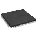
ARM® Cortex®-M4 STM32F4 Microcontroller IC 32-Bit 180MHz 2MB (2M x 8) FLASH 176-LQFP (24x24) The STM32F427IIT6 specification defines the engineering requirements for a high-performance microcontroller device designed for embedded processing applications requiring advanced computational capability, rich peripheral integration, and reliable real-time control. This specification establishes the functional, electrical, mechanical, environmental, and quality requirements necessary to ensure consistent operation across industrial, consumer, and communication systems. The device is intended for use in complex embedded systems where high-speed processing, efficient memory handling, and extensive peripheral connectivity are required. It supports applications such as industrial automation, motor control, signal processing, communication interfaces, and advanced embedded control systems. Engineering Requirements The microcontroller shall be manufactured using advanced semiconductor fabrication processes to ensure high processing performance, low power consumption, and long-term reliability. The device shall provide stable operation across its intended voltage, temperature, and environmental conditions while maintaining deterministic real-time behavior. The integrated architecture shall support high-speed processing capabilities, embedded memory resources, and multiple communication interfaces for system-level integration. Peripheral functionality shall operate reliably under defined electrical and environmental conditions without degradation of performance. Electrical characteristics shall ensure stable logic levels, accurate timing behavior, and robust signal integrity across all supported operating modes. The device shall maintain functional reliability during power transitions, reset conditions, and dynamic load variations. Mechanical and package construction shall be suitable for surface-mount assembly processes and shall ensure mechanical integrity during soldering, handling, and operation. Workmanship shall be free from defects including contamination, physical damage, or structural inconsistencies that could impact reliability or performance. Inspection, validation, and testing shall be performed using controlled procedures and calibrated equipment to ensure compliance with all applicable engineering and quality standards. Any deviation from this specification shall require formal engineering review, documented justification, and approval through the established change control process. Documentation Supporting documentation shall include engineering datasheets, reference manuals, qualification reports, electrical characterization data, inspection records, and revision-controlled manufacturing documentation. All records shall be maintained under formal configuration management and quality assurance systems. Revision Control Any modification to this specification shall be processed through the established engineering change management system. All revisions shall undergo technical review, validation, and formal approval prior to implementation to ensure continued compliance with design intent and applicable industry requirements. #EngineeringSpecification #Microcontroller #EmbeddedSystems #STMicroelectronics #DigitalControl #IndustrialElectronics #Firmware #Semiconductor #QualityAssurance #EngineeringDocumentation #RealTimeSystems
0 Uses0 StarsFH12S-45S-0.5SH(55)
45 Position FFC, FPC Connector Contacts, Bottom 0.020" (0.50mm) Surface Mount, Right Angle The FH12S-45S-0.5SH(55) specification defines the engineering requirements for a fine pitch flexible printed circuit and flexible flat cable connector designed for compact electronic assemblies requiring high density signal interconnection. This specification establishes the mechanical, electrical, environmental, and quality requirements necessary to ensure reliable signal transmission, stable mechanical retention, and consistent performance in board-to-cable interconnect applications. The component is intended for use in electronic systems where space-constrained design and high pin density interconnection are required, such as display modules, embedded control systems, and portable electronic devices. It provides a secure mating interface for flexible cables while maintaining low contact resistance and stable signal integrity under mechanical and environmental stress. Engineering Requirements The connector shall be manufactured using high-quality insulating materials and precision-formed metal contacts to ensure consistent electrical continuity and mechanical reliability. The design shall provide a secure locking mechanism suitable for repeated mating cycles without degradation of contact performance. Electrical characteristics shall support stable signal transmission with minimal insertion loss and low contact resistance. The connector shall maintain performance under specified operating temperature ranges and environmental conditions including humidity, vibration, and thermal cycling. Mechanical construction shall ensure accurate alignment between connector housing and flexible cable interface. The contact system shall maintain reliable pressure engagement without deformation or loosening during operation. The locking mechanism shall prevent accidental disconnection while allowing controlled insertion and removal during assembly or servicing. Workmanship shall be free from defects including cracking, deformation, contamination, corrosion, or plating irregularities that may affect electrical or mechanical performance. Manufacturing and inspection processes shall be performed under controlled quality systems using calibrated equipment to ensure compliance with engineering requirements. Any deviation from this specification shall require formal engineering review, documented justification, and approval through the established engineering change control process prior to implementation. Documentation Supporting documentation shall include engineering drawings, connector datasheets, material declarations, inspection reports, qualification test results, and revision-controlled manufacturing instructions. All documentation shall be maintained in accordance with established configuration management and quality assurance procedures. Revision Control Any modification to this specification shall be managed through formal engineering change control procedures. All revisions shall be technically reviewed, validated for compliance impact, and formally approved prior to release. #EngineeringSpecification #FPCConnector #FFCConnector #HiroseElectric #InterconnectSystems #ElectronicDesign #Manufacturing #QualityAssurance #EngineeringDocumentation #SignalIntegrity
1 Uses0 StarsSTM32G491RET6
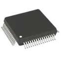
ARM® Cortex®-M4F STM32G4 Microcontroller IC 32-Bit 170MHz 512KB (512K x 8) FLASH 64-LQFP (10x10) The STM32G491RET6 from STMicroelectronics is a high-performance 32-bit microcontroller based on the Arm® Cortex®-M4 core with Floating Point Unit (FPU), designed for advanced embedded applications requiring high computational performance, precise analog processing, and real-time control. It belongs to the STM32G4 series and integrates enhanced analog peripherals, motor-control timers, communication interfaces, security features, and hardware accelerators such as CORDIC and FMAC. The device operates at up to 170 MHz, provides 512 KB Flash memory, and includes 96 KB SRAM, making it suitable for applications such as motor control, digital power conversion, industrial automation, robotics, and embedded control systems. Key Features Core: Arm® Cortex®-M4 32-bit CPU with FPU, DSP instructions, and MPU Maximum CPU Frequency: Up to 170 MHz (up to 213 DMIPS) Memory: 512 KB Flash memory with ECC support 96 KB SRAM with parity checking features Quad-SPI memory interface Operating Voltage: 1.71 V to 3.6 V Package: LQFP-64 Advanced Analog Features: 3 × 12-bit ADCs with high-speed conversion 4 × 12-bit DAC channels 4 × Rail-to-Rail operational amplifiers 4 × Fast analog comparators Internal voltage reference buffer Hardware Accelerators: CORDIC accelerator for trigonometric calculations FMAC (Filter Math Accelerator) for digital filtering applications Timers & Motor Control: Advanced PWM timers for motor-control applications Multiple 16-bit and 32-bit timers Support for encoder and PWM control Communication Interfaces: 2 × FDCAN interfaces 5 × USART/UART 3 × SPI interfaces 3 × I²C interfaces USB 2.0 Full-Speed interface SAI audio interface Security Features: True Random Number Generator (TRNG) CRC calculation unit Unique device ID Debug & Programming: SWD and JTAG debugging support Typical Applications Motor control and BLDC controllers Digital power converters Industrial automation equipment Robotics and motion control Smart sensors and embedded control systems Power management applications #STM32G491RET6 #STM32G4 #STMicroelectronics #ARM_CortexM4 #Microcontroller #MCU #EmbeddedSystems #MotorControl #DigitalPower #IndustrialAutomation #Robotics #IoT #ElectronicsDesign #PCBDesign
30 Uses0 StarsMM238RW
FLYTO MM238RW 5.8G 4.9G 6.0G Wireless FPV Video Transmission Open-Source Receiver with SPI High Sensitivity The MM238RW is a high-sensitivity analog FPV (First-Person View) video receiver module designed for wireless image transmission systems operating in the 4.9 GHz, 5.8 GHz, and 6.0 GHz bands. It supports SPI control for frequency configuration and integration into custom embedded systems, FPV goggles, ground stations, and video receivers. The module provides low-latency CVBS video output, strong anti-interference performance, and wide compatibility with analog FPV video transmitters. Key Features Wide receiving frequency range: 4900 MHz to 5945 MHz SPI interface for channel and frequency control High receiver sensitivity of up to −90 dBm Low-latency analog CVBS video output FM/PLL demodulation architecture Excellent anti-interference performance 50 Ω RF input impedance Supply voltage: 3.3 V to 5.0 V Typical current consumption: 220 mA Compact module suitable for FPV goggles, monitors, and ground stations Supports custom firmware and open-source development platforms Applications FPV racing drones UAV and aerial photography systems Ground station receivers FPV goggles Wireless analog video monitoring Custom RF video receiver designs Hashtags: #MM238RW #FPV #VideoReceiver #5_8GHz #SPIInterface #DroneElectronics #WirelessVideo #CVBS #RFModule #UAV #FPVGoggles #EmbeddedSystems #AerialPhotography #LowLatency #OpenSourceFPV
0 Uses0 StarsIS66WVH64M8DBLL-166B1LI
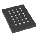
PSRAM (Pseudo SRAM) Memory IC 512Mbit HyperBus 166 MHz 36 ns 24-TFBGA (6x8) The IS66/67WVH64M8DALL/BLL are 512Mb Dual Die device containing two units of 256Mbit Pseudo Static Random Access Memory, organized as 64M words by 8 bits. The device supports a HyperBus interface, Very Low Signal Count (Address, Command and data through 8 DQ pins), Hidden Refresh Operation, and Automotive Temperature Operation, designed especially for Mobile and Automotive applications Key Features 512-Mbit (64M × 8) HyperRAM™ PSRAM High-speed HyperBus interface Clock frequency up to 166 MHz Fast 36 ns access time Single-ended clock architecture with reduced pin count Operating voltage range: 2.7 V to 3.6 V Industrial temperature range: −40°C to +85°C Low-power volatile memory solution Surface-mount 24-TFBGA (6 mm × 8 mm) package Suitable for graphics, AI edge devices, networking, and embedded systems requiring large external memory capacity. #CommonPartsLibrary #IntegratedCircuit #HyperRAM #PSRAM #ISSI #MemoryIC #HyperBus #EmbeddedSystems #IndustrialElectronics #IoT #HighSpeedMemory #BGA #VolatileMemory #EdgeComputing #HMI #ElectronicsDesign
2 Uses0 StarsISO1412BDW
ISO1412BDW SOIC-16_L10.3-W7.5-P1.27-LS10.3-BL LCSC Part Number: C1544462 ISOW1412 Texas Instruments ISO14xx Series (ISO1410, ISO1412, ISO1430, ISO1450, ISO1452) – galvanically isolated RS-485/RS-422 transceivers designed for industrial communication networks. Combines differential bus transceiver functionality with integrated isolation barrier, providing robust protection against ground potential differences, electrical noise, ESD, EFT, and transient events. Supports up to 50 Mbps data rates, 1/8-unit-load operation for up to 256 nodes, fail-safe receiver functionality, hot-plug operation, and extended industrial temperature range. Available in basic and reinforced isolation versions for industrial automation, energy systems, motor drives, and smart infrastructure. Search Keywords: ISO1410, ISO1412, ISO1430, ISO1450, ISO1452, TI ISO14xx, Isolated RS485 Transceiver, Isolated RS422 Transceiver, Galvanic Isolation, Industrial Communication IC, Reinforced Isolation Transceiver, Basic Isolation Transceiver, RS485 Isolator, Differential Bus Transceiver, 256 Node RS485, Fail Safe Receiver, Industrial Automation Communication, PLC Communication, Modbus Interface, Energy Meter Communication, Motor Drive Communication, High EMC RS485, IEC61000 Protected Transceiver Hashtags: #ISO1410 #ISO1412 #ISO1430 #ISO1450 #ISO1452 #TexasInstruments #RS485 #RS422 #IsolatedTransceiver #GalvanicIsolation #IndustrialCommunication #Modbus #PLC #FactoryAutomation #MotorControl #EnergyManagement #SmartGrid #EmbeddedSystems #ElectronicsDesign #PCBDesign
3 Uses0 Stars