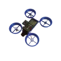
Top User Projects
Explore innovation and practical design in Flux.ai's top user projects. This collection highlights outstanding printed circuit board (PCB) projects crafted by our community members. Featuring a range of complexities and applications, these projects showcase the real-world potential and diversity of PCB design. The top user projects section is an invaluable resource for inspiration and learning. Whether you’re a veteran PCB designer seeking fresh ideas or a newcomer aiming to understand various design strategies, these projects offer a wealth of knowledge and insight into the dynamic world of PCB design. By highlighting the achievements of our community, the top user projects stand as a testament to the innovative spirit and collaborative nature of Flux.ai’s users, fostering a culture of knowledge sharing and continuous advancement in the field of electronics design.
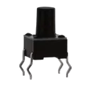
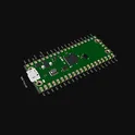
Raspberry Pi Pico Shield Template
Explore the Raspberry Pi Pico Template Unleash the power of these flexible microcontroller boards, starting at just $4. The Raspberry Pi Pico series features a range of compact, high-performance boards powered by the RP2040 chip. #project-template #template #raspberry #pi #pico
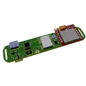
0 Uses13 StarsPCB Business Card V2
Change History from V1: -13.56MHz tuning -larger instruction font -put some stuff on the back I wanted to create a business card that has some functionality and shows off a bit of my portfolio IRL: -NFC to my flux page -here's the awesome [instructables](https://www.instructables.com/PCB-Business-Card-With-NFC/) -Put a bunch of modules on it Find the BoM [here](https://www.digikey.com/short/2db2vnmp)
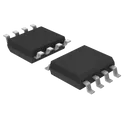
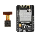
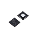
0 Uses13 StarsRP2040
RP2040 chip for Raspberry Pi Pico - ARM® Cortex®-M0+ MCU 32-Bit The RP2040 is a high-performance, low-cost microcontroller built around two ARM Cortex-M0+ cores. It is optimized for flexibility, ease of use, and deterministic real-time performance. Unlike many microcontrollers, it includes a unique programmable I/O subsystem (PIO), allowing custom hardware interfaces without extra components. Key Features Processing Dual-core ARM Cortex-M0+ processors Up to 133 MHz clock speed Efficient integer performance with low power consumption Memory 264 KB on-chip SRAM External QSPI flash support (typically 2 MB–16 MB depending on board) Programmable I/O (PIO) 2 PIO blocks, each with 4 state machines Enables custom protocols (e.g., SPI, I2C, UART, WS2812, VGA, etc.) Offloads timing-critical tasks from CPU 🔗 Connectivity Interfaces 2× UART 2× SPI 2× I2C USB 1.1 controller (device or host support) 16× PWM channels Analog Features 12-bit ADC (up to 5 channels, including internal temperature sensor) Power & Voltage Operating voltage: 1.8V – 3.3V Low-power modes available Package Options QFN-56 (7×7 mm) Development Ecosystem Supports C/C++ SDK MicroPython and CircuitPython support Strong community and documentation Typical Applications Embedded systems and IoT devices Robotics and automation DIY electronics and prototyping USB devices (HID, MIDI, etc.) Custom communication interfaces using PIO #CommonPartsLibrary #IntegratedCircuit #Microcontroller
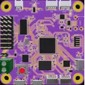
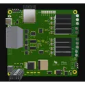
1.1k Uses12 StarsPet Tracker Device
This is a Pet Tracker Reference Design based on STM32L4. Tracker connects with network by SIM800L module connected to the STM. Also MCU connected to the GPS by uart and send data to server #STM32 #GPS #G4 #G3 #LTE #IoT #Tracker #smartHomeDevices #referenceDesign #edge-computing #edgeComputing #stm #template #referenceDesign
0 Uses12 StarsHADES
HADES Flight Control System. Complete flight control system designed from scratch. The flight control system is primarily designed for fixed-wing, autonomous drones to enable them to perform tasks autonomously, such as take-off, landing, waypoint navigation, payload delivery, etc.
0 Uses12 Stars


![[Multi-layer] JLCPCB Constraints](https://img-cdn.flux.ai/eyJidWNrZXQiOiJncmF2aXRvbi1lbGVjdHJpYy1zeW1ib2xzIiwia2V5IjoiZG9jdW1lbnRfYXNzZXRzL211bHRpLWxheWVyLXRodW1iLWE3NzgwN2M1LWIxNmQtNGNmMi04YzZkLWI3MDRiNzVhYTEyZC5wbmciLCJlZGl0cyI6eyJyZXNpemUiOnsid2lkdGgiOjEyNCwiaGVpZ2h0IjoxMjQsImZpdCI6ImNvbnRhaW4iLCJiYWNrZ3JvdW5kIjp7InIiOjAsImciOjAsImIiOjAsImFscGhhIjowfX19LCJvdXRwdXRGb3JtYXQiOiJ3ZWJwIn0=)