BH9VPC
Battery Holder (Open) 9V 1 Cell PC Pin 9V battery holder through hole The BH9VPC is a through-hole, printed circuit board–mount battery holder designed to accommodate a single standard 9 V (PP3) battery. It provides a secure mechanical enclosure and reliable electrical interface for powering electronic assemblies directly from a PCB. The holder is constructed from durable insulating material with integrated metal contacts to ensure stable retention and consistent electrical connection during operation. Its form factor supports straightforward integration into compact designs while maintaining ease of battery replacement. Engineering Specification: The component is intended for through-hole mounting using PC pins that provide both mechanical stability and electrical connection to the circuit board. It supports one 9 V battery with standard snap terminal interface internally routed to PCB pins. The housing material is typically molded plastic with good mechanical strength and electrical insulation properties suitable for general electronic applications. Contact terminals are metal, commonly nickel-plated or equivalent, to ensure low contact resistance and corrosion resistance over repeated battery insertions. The holder is designed for vertical mounting orientation relative to the PCB, with a compact footprint suitable for space-constrained layouts. It provides sufficient retention force to secure the battery under normal handling and vibration conditions encountered in consumer and light industrial electronics. The operating characteristics are aligned with typical 9 V battery usage, supporting low to moderate current applications depending on battery capability. The part is compatible with standard wave soldering processes used in through-hole assembly. It is intended for use in ambient environmental conditions typical of indoor electronic equipment and is not inherently sealed against moisture or contaminants. The design allows easy manual insertion and removal of the battery without specialized tools, supporting maintenance and replacement in field applications. #commonpartslibrary #batteryholder... show more1.9k Uses
0 Stars
ADXL355BEZ
Accelerometer X, Y, Z Axis ±2g, 4g, 8g 1.5kHz 14-CLCC (6x6) General Description The ADXL355BEZ is a low noise, low drift, low power, three-axis MEMS accelerometer intended for high-precision sensing applications. It delivers high-resolution digital acceleration data with excellent long-term stability and minimal temperature-induced variation. The device integrates a complete sensing chain, including the MEMS sensor element, analog conditioning, analog-to-digital conversion, and digital filtering. Output data is provided through SPI or I²C interfaces, enabling straightforward integration into embedded and industrial systems. Key Features Three-axis acceleration sensing (X, Y, Z) Selectable full-scale ranges: ±2 g, ±4 g, ±8 g Low noise density (~25 µg/√Hz) Low offset and minimal temperature drift High-resolution 20-bit digital output Integrated digital filtering SPI and I²C communication interfaces Low power consumption (~200 µA typical) Wide supply voltage range (2.25 V to 3.6 V) Integrated temperature sensor Hermetically sealed package Applications Structural health monitoring Vibration measurement and analysis Tilt and inclination sensing Industrial condition monitoring Navigation and inertial systems Seismic detection Robotics and stabilization platforms Functional Description The ADXL355BEZ includes an integrated sensing and processing architecture composed of: Three-axis MEMS sensing element Analog front-end signal conditioning High-resolution ADC Digital filtering and decimation stages Temperature sensing element Digital communication interface (SPI/I²C) Configuration and control registers Electrical Characteristics (Typical) Supply voltage: 2.25 V to 3.6 V Supply current: ~200 µA Output data rate: up to 4 kHz Noise density: ~25 µg/√Hz Resolution: 20-bit Interface: SPI / I²C Mechanical and Package Information Package type: LGA (Land Grid Array) Approximate dimensions: 3 mm × 5 mm × 1 mm Hermetically sealed for improved environmental robustness Interface and Communication Supports SPI (4-wire) and I²C protocols Outputs 20-bit acceleration data per axis Data format: two’s complement Measurement Ranges ±2 g ±4 g ±8 g Environmental Specifications Operating temperature range: -40°C to +125°C Storage temperature range: -55°C to +150°C Power Management Supports measurement and standby modes Designed for low-power operation in continuous sensing applications Compliance and Reliability Industrial-grade device Designed for long-term stability RoHS compliant #commonpartslibrary #sensor #accelerometer... show more28 Uses
0 Stars
MUSBRM1C1M0
USB-C (USB TYPE-C) Receptacle Connector 24 Position Panel Mount, Through Hole, Right Angle The MUSBRM1C1M0 is a ruggedized USB Type-C receptacle connector designed for high-reliability data and power connectivity in industrial, embedded, transportation, and harsh-environment applications. The connector features a reversible USB Type-C interface that supports modern high-speed communication protocols while providing robust mechanical durability and secure board-level attachment. Its reinforced construction helps withstand vibration, shock, and repeated mating cycles, making it suitable for demanding applications where reliability and long service life are critical. The device is commonly used in industrial controllers, communication equipment, medical devices, consumer electronics, and next-generation embedded systems requiring compact and versatile connectivity. Engineering Specifications Manufacturer: Amphenol Communications Solutions Part Number: MUSBRM1C1M0 Connector Type: USB Type-C Receptacle Interface Standard: Universal Serial Bus Type-C Connector Gender: Receptacle Mounting Style: Surface Mount Orientation: Right Angle Contact Configuration: USB Type-C Multi-Function Interface Data Support: High-Speed Data Transmission Power Delivery Support: Compatible with USB Power Delivery Architectures Shielding: Integrated EMI Shielding Contact Material: Copper Alloy Contact Finish: Gold-Plated Contact Interface Housing Material: High-Strength Metal Shield Construction Durability: High Mating Cycle Life Environmental Performance: Designed for Industrial Applications Operating Temperature Range: Industrial Grade RoHS Compliant: Yes Applications: Embedded Systems, Industrial Automation, Consumer Electronics, Communication Equipment, Medical Devices, IoT Products, Portable Electronics, Data Acquisition Systems Key Features Reversible USB Type-C connection interface Ruggedized mechanical construction High-speed data communication capability Secure PCB mounting design Enhanced resistance to vibration and mechanical stress Integrated shielding for improved electromagnetic compatibility Compact footprint for space-constrained designs Supports modern USB power and data architectures Long operational lifespan with high insertion cycle durability Suitable for industrial and commercial electronic systems #MUSBRM1C1M0 #Amphenol #USBTypeC #USBConnector #TypeCReceptacle #HighSpeedConnectivity #PowerDelivery #IndustrialElectronics #EmbeddedSystems #CommunicationEquipment #IoTDevices #ConsumerElectronics #PCBDesign #ElectronicComponents #SurfaceMount #DataTransmission #USBPD #IndustrialAutomation #MedicalElectronics #ConnectorTechnology... show more1 Use
0 Stars
ADXL373BCCZ-RL7
Accelerometer X, Y, Z Axis ±400g 160Hz ~ 2.56kHz 16-LGA (3x3.25) The ADXL373BCCZ-RL7 is an ultralow power, high-g digital MEMS accelerometer developed by Analog Devices for motion sensing and impact detection applications. The device is optimized for battery-powered and always-on systems requiring continuous acceleration monitoring with minimal power consumption. It supports selectable measurement ranges suitable for shock, vibration, and activity monitoring in industrial, wearable, medical, asset tracking, and IoT applications. The accelerometer integrates embedded motion detection features, a FIFO buffer, and interrupt capabilities to reduce host processor workload and overall system power consumption. Engineering Specification Device Type Ultralow power 3-axis digital MEMS accelerometer Manufacturer Analog Devices Inc. Manufacturer Part Number ADXL373BCCZ-RL7 Measurement Axes Three-axis acceleration sensing Acceleration Range Selectable full-scale ranges supporting high-g measurements up to ±400 g Output Interface SPI digital serial communication interface Resolution High-resolution digital acceleration output with integrated filtering and signal conditioning Power Supply Requirement Operates from a low-voltage DC supply suitable for portable and embedded systems Power Consumption Designed for extremely low current operation during measurement and wake-up monitoring modes Embedded Features Integrated activity detection Motion and impact sensing FIFO data buffering Interrupt generation Wake-up detection functionality Sampling and Performance Programmable output data rates and filtering options for optimized noise and bandwidth performance Operating Temperature Range Industrial temperature range suitable for harsh environmental applications Package Type LGA surface-mount package Mounting Style Surface mount technology Application Areas Impact event recording Condition monitoring Asset tracking Industrial sensing Wearable electronics Portable instrumentation Shock and vibration monitoring Always-on motion detection systems #commonpartslibrary #integratedcircuit #accelerometer #sensor... show more3 Uses
0 Stars
TGS2611-C00
The TGS2611-C00 specification defines the engineering requirements for a semiconductor gas sensor designed for the detection of combustible gases in industrial, commercial, and embedded monitoring systems. This specification establishes the functional, electrical, mechanical, environmental, and quality requirements necessary to ensure accurate gas detection, stable sensing characteristics, and long-term operational reliability. The sensor is intended for use in gas leak detection equipment, safety monitoring systems, residential and commercial appliances, industrial automation, and environmental monitoring applications. It utilizes semiconductor sensing technology to detect target combustible gases with high sensitivity and repeatable performance, enabling reliable monitoring and early warning in safety-critical environments. Engineering Requirements The gas sensor shall be manufactured using qualified semiconductor sensing materials and controlled production processes to ensure consistent sensitivity, repeatability, and long-term stability. The sensing element shall maintain reliable performance under specified operating voltage, temperature, humidity, and environmental conditions. Electrical characteristics shall provide stable output response, repeatable detection performance, and predictable recovery behavior following gas exposure. The sensor shall maintain reliable operation during continuous monitoring while minimizing drift and preserving measurement consistency throughout its service life. The sensing element shall provide dependable detection of the intended combustible gases while maintaining resistance to environmental influences and normal operational contaminants. The sensor shall exhibit stable response characteristics suitable for integration with embedded control systems and gas monitoring electronics. Mechanical construction shall provide adequate protection for the sensing element while allowing sufficient exposure to the surrounding atmosphere for effective gas diffusion. The package shall withstand handling, vibration, thermal cycling, and standard assembly processes without degradation of sensing performance or structural integrity. Workmanship shall be free from defects including contamination, mechanical damage, corrosion, package deformation, or structural inconsistencies that could adversely affect sensing accuracy or reliability. Inspection, validation, and testing shall be performed using calibrated equipment and controlled quality procedures to verify compliance with engineering and manufacturing requirements. Any deviation from this specification shall require formal engineering evaluation, documented technical justification, and approval through the established engineering change control process before implementation. Documentation Supporting documentation shall include engineering drawings, electrical specifications, gas sensitivity characteristics, qualification reports, inspection records, reliability data, material declarations, and revision-controlled manufacturing documentation. All documentation shall be maintained under formal configuration management and quality assurance systems to ensure complete product traceability. Revision Control Any modification to this specification shall be managed through the formal engineering change management process. All revisions shall undergo technical review, validation, and approval before release to ensure continued compliance with design intent and applicable engineering standards. #EngineeringSpecification #GasSensor #CombustibleGasSensor #SemiconductorSensor #GasDetection #IndustrialSafety #EmbeddedSystems #EnvironmentalMonitoring #QualityAssurance #EngineeringDocumentation... show more0 Uses
0 Stars
1725656
2 Position Wire to Board Terminal Block Horizontal with Board 0.100" (2.54mm) Through Hole 1725656 – PCB-mounted screw terminal block designed for secure wire-to-board connections in industrial, control, automation, instrumentation, and power distribution applications. Features a screw-clamp termination system that provides reliable electrical contact and strong wire retention under vibration and demanding operating conditions. The through-hole construction offers enhanced mechanical stability, making it suitable for long-term field installations and high-reliability electronic assemblies. Designed to simplify wiring, maintenance, and system integration while ensuring dependable signal and power connectivity. #TerminalBlock #ScrewTerminal #WireToBoard #IndustrialElectronics #PowerDistribution #AutomationSystems #ControlPanels #ThroughHoleConnector #PCBConnector #ReliableConnectivity #connector #Terminalblock #tht... show more394 Uses
0 Stars
SWLP.2450.10.4.A.02
RF ANTENNA Bluetooth, Wi-Fi, WLAN, Zigbee™ Ceramic Patch Solder Surface Mount The SWLP.2450.10.4.A.02 specification defines the engineering requirements for a surface-mount radio frequency antenna designed for wireless communication applications operating within the 2.4 GHz frequency band. This specification establishes the functional, electrical, mechanical, environmental, and quality requirements necessary to ensure efficient RF transmission and reception, stable antenna performance, and long-term operational reliability in embedded electronic systems. The antenna is intended for use in wireless communication devices supporting technologies such as Bluetooth, Wi-Fi, Zigbee, Thread, and other 2.4 GHz ISM band protocols. It is optimized for compact PCB integration while providing efficient radiation characteristics, stable impedance matching, and dependable performance in space-constrained electronic products including IoT devices, industrial controllers, consumer electronics, and smart sensing platforms. Engineering Requirements The antenna shall be manufactured using qualified conductive and dielectric materials with controlled production processes to ensure consistent RF performance, mechanical durability, and long-term reliability. The construction shall maintain stable electrical characteristics throughout the specified operating temperature and environmental conditions. Electrical characteristics shall provide efficient radiation efficiency, stable impedance matching, low return loss, and reliable signal transmission and reception across the intended operating frequency range. The antenna shall maintain consistent performance when integrated according to the recommended PCB layout and grounding practices. The RF structure shall minimize insertion losses and support reliable wireless communication while maintaining acceptable gain, bandwidth, and radiation pattern characteristics. The antenna shall exhibit stable performance under normal operating conditions without significant degradation caused by thermal variation or environmental exposure. Mechanical construction shall be suitable for automated surface-mount assembly and compatible with standard solder reflow manufacturing processes. The package shall withstand vibration, thermal cycling, mechanical handling, and environmental stress without degradation of electrical or structural performance. Workmanship shall be free from defects including cracks, contamination, plating irregularities, or structural inconsistencies that could adversely affect RF performance or reliability. Inspection, validation, and testing shall be performed using calibrated RF measurement equipment and controlled quality procedures to verify compliance with engineering and manufacturing requirements. Any deviation from this specification shall require formal engineering evaluation, documented technical justification, and approval through the established engineering change control process before implementation. Documentation Supporting documentation shall include engineering drawings, RF performance specifications, impedance matching recommendations, qualification reports, inspection records, reliability data, material declarations, and revision-controlled manufacturing documentation. All documentation shall be maintained under formal configuration management and quality assurance systems to ensure complete product traceability. Revision Control Any modification to this specification shall be managed through the formal engineering change management process. All revisions shall undergo technical review, validation, and approval before release to ensure continued compliance with design intent and applicable engineering standards. #EngineeringSpecification #RFAntenna #WirelessCommunication #Antenna #Bluetooth #WiFi #IoT #EmbeddedSystems #QualityAssurance #EngineeringDocumentation... show more0 Uses
0 Stars
7461147
WP-BUFU REDCUBE Bush, full height: 7mm, total height: 10.5mm, thread length: 4mm, pin length: 3.5mm, raster: 2.54mm, REDCUBE Press-Fit; M5, blind 4mm 16 Pin Screw Terminal, Power Tap M5 Through Hole The 7461147 is a high-current PCB-mounted power terminal from the REDCUBE® WP-BUFU series by Würth Elektronik. It is designed to provide a robust and low-resistance connection for transferring high currents between cables, busbars, and printed circuit boards. The terminal utilizes press-fit technology, eliminating the need for soldering while ensuring a gas-tight, vibration-resistant electrical connection. It is particularly suitable for power distribution, industrial equipment, automotive electronics, battery systems, and renewable energy applications. Key Features High current rating up to 180 A M5 screw terminal for secure high-power connections Press-fit termination for solderless PCB assembly 16-pin through-hole mounting configuration Gas-tight electrical connection for long-term reliability Excellent resistance to vibration and mechanical shock Low contact resistance for efficient power transfer Simplifies manufacturing by eliminating soldering processes Suitable for high-current power distribution and battery applications RoHS compliant design Typical Applications Power supplies and power converters Battery management and energy storage systems DC-DC and DC-AC converters Industrial automation equipment Automotive power electronics Solar and wind energy systems High-current PCB power distribution networks #CommonPartsLibrary #REDCUBE #PowerTerminal #PressFit #HighCurrentConnector #PCBTerminal #WurthElektronik #IndustrialElectronics #AutomotiveElectronics #PowerDistribution #EnergyStorage #RenewableEnergy #7461147... show more193 Uses
0 Stars
G6K-2P-Y-DC5
Telecom Relay DPDT (2 Form C) Through Hole The G6K-2P-Y DC5 is a compact, ultra-miniature signal relay designed for high-density PCB mounting applications. Manufactured by Omron, this relay features a DPDT (2 Form C) contact configuration and operates with a 5 VDC coil. It is optimized for switching low-level signals and is commonly used in telecommunications, test and measurement equipment, and consumer electronics where space-saving and high reliability are critical. Key Features Ultra-miniature, low-profile design for high-density mounting DPDT (2 Form C) contact configuration High sensitivity coil (low power consumption) Gold-clad contacts for low-level signal switching High reliability and long mechanical life Fully sealed construction (flux protection) Suitable for surface-mount and through-hole variants (depending on suffix) Electrical Characteristics Coil Specifications Rated Coil Voltage: 5 VDC Coil Resistance: ~125 Ω Coil Current: ~40 mA Power Consumption: ~200 mW Must Operate Voltage: ≤ 75% of rated voltage Must Release Voltage: ≥ 10% of rated voltage Contact Specifications Contact Configuration: DPDT (2 Form C) Contact Material: Gold-clad silver alloy Contact Rating: 1 A at 30 VDC 0.5 A at 125 VAC Maximum Switching Voltage: 125 VAC / 60 VDC Maximum Switching Current: 1 A Maximum Switching Power: 30 W (DC) 62.5 VA (AC) Timing Characteristics Operate Time: ≤ 3 ms Release Time: ≤ 3 ms Insulation Characteristics Insulation Resistance: ≥ 1,000 MΩ (at 500 VDC) Dielectric Strength: Between Coil and Contacts: 1,000 VAC (1 min) Between Open Contacts: 500 VAC (1 min) Mechanical Characteristics Mounting Type: Through-hole (Y variant, PCB terminal) Weight: ~1 g Enclosure: Sealed (flux-resistant) Environmental Specifications Operating Temperature Range: -40°C to +70°C Storage Temperature Range: -40°C to +85°C Vibration Resistance: 10 to 55 Hz, 1.5 mm double amplitude Shock Resistance: 1,000 m/s² Life Expectancy Mechanical Life: ≥ 100 million operations Electrical Life: ≥ 100,000 operations (at rated load) Applications Telecommunications equipment Test and measurement instruments Audio signal routing Industrial control systems Consumer electronics Package Information Manufacturer: Omron Electronics Series: G6K Part Number: G6K-2P-Y DC5 #commonpartslibrary #relay... show more180 Uses
0 Stars
19428-0015
Connector Header Panel Mount, Through Hole 12 position 0.230" (5.84mm) The 0194280015 is a wire-to-board rectangular header connector from Molex, part of the MX150L series. It is designed for high-reliability power and signal connections, particularly in automotive and industrial environments. This connector is a 12-position, dual-row, vertical (straight) male header that mounts through the PCB and mates with corresponding cable connectors. It features a sealed design (IP67 rated), making it suitable for harsh conditions such as dust, moisture, and vibration. Key Features Connector Type Wire-to-board male header (vertical / straight) Number of Positions 12 contacts (2 rows) Pitch 5.84 mm terminal pitch ~6.0 mm row spacing High Power Capability Up to ~18 A per contact (application dependent) Voltage rating up to 600V AC/DC Sealed / Rugged Design IP67 rated (dust-tight and waterproof) Suitable for harsh environments Mounting Type Panel mount / through-hole PCB soldering Locking Mechanism Locking ramp + polarization (keying) for secure mating Material & Construction Housing: Glass-filled PBT (UL94 V-0 flame rating) Contacts: Copper alloy with tin plating Durability Designed for automotive-grade reliability Typical mating cycles: ~25 cycles Operating Temperature Approximately -40°C to +125°C #CommonPartsLibrary #Connector #MX150L 19428... show more88 Uses
0 Stars
2604-3104
4 Position Wire to Board Terminal Block Vertical with Board 0.197" (5.00mm) Through Hole The WAGO 2604-3104 is a through-hole PCB terminal block designed for secure wire-to-board power and signal connections in industrial and commercial electronic equipment. It features WAGO Push-in CAGE CLAMP® spring connection technology with integrated lever actuation, allowing fast, tool-free wire insertion and removal. The connector is intended for reliable field wiring applications where vibration resistance, ease of maintenance, and compact PCB integration are required. Engineering Specification Manufacturer: WAGO Manufacturer Part Number: 2604-3104 Product Family: PCB Terminal Block Series: 2604 Connector Type: Wire-to-Board Terminal Block Mounting Style: Through-Hole PCB Mount Orientation: Vertical / Top Entry Number of Positions: 4 Pitch Spacing: 5.00 mm Connection Technology: Push-in CAGE CLAMP® Actuation Method: Lever Operated Wire Size Range: 24 AWG to 12 AWG Supported Conductors: Solid, stranded, and ferruled wires Rated Voltage: Up to 400 V IEC, 300 V UL Rated Current: Up to 32 A IEC, 20 A UL Operating Temperature Range: -60°C to +105°C Insulation Material: Polyamide PA66 Contact Material: Electrolytic Copper Contact Plating: Tin-Plated Spring Material: Chrome Nickel Spring Steel Flammability Rating: UL94 V-0 Color: Gray housing with orange lever PCB Contact Type: THT solder pins Application Areas: Industrial controls, power distribution, automation systems, instrumentation, and general PCB power interconnects. #commonpartslibrary #connector #terminalblock... show more59 Uses
0 Stars
ADXL345
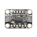
ADXL345 iMEMS® Accelerometer, 3 Axis Sensor Evaluation Board The ADXL345 measures acceleration in three axes (X, Y, Z) and outputs digital data via either I²C or SPI interfaces. It is widely used in applications like tilt sensing, vibration monitoring, free-fall detection, and motion-based user interfaces. Its high resolution (up to 13-bit) allows it to detect very small changes in motion, making it suitable for both consumer electronics and industrial applications. Key Features 3-axis acceleration measurement (X, Y, Z) Selectable measurement ranges: ±2g, ±4g, ±8g, ±16g High resolution (13-bit) with up to 4 mg/LSB sensitivity Digital output interfaces: I²C and SPI Low power consumption: ideal for battery-powered devices Built-in motion detection functions: Tap and double-tap detection Free-fall detection Activity and inactivity monitoring Wide bandwidth range: supports various data rates for different applications Operating voltage: typically 2.0V to 3.6V Compact package: small LGA form factor suitable for space-constrained designs Common Applications Smartphones and tablets (screen rotation, motion sensing) Wearable devices and fitness trackers Gaming controllers Robotics and drones Vibration and shock monitoring systems #commonpartslibrary #developmentboard #evaluationboard #sensor... show more128 Uses
2 Stars
LM5148RGYR
Buck Regulator Positive Output Step-Down DC-DC Controller IC 24-VQFN (3.5x5.5) The LM5148RGYR specification defines the engineering requirements for a synchronous buck controller integrated circuit designed for high-efficiency DC-DC power conversion applications. This specification establishes the functional, electrical, mechanical, thermal, environmental, and quality requirements necessary to ensure reliable voltage regulation, efficient power management, and long-term operational stability in industrial, automotive, telecommunications, and embedded electronic systems. The device is intended for use in high-performance power supply designs requiring wide input voltage capability, precise output voltage regulation, and high-current conversion efficiency. It controls external power MOSFETs to implement synchronous buck converter topologies suitable for distributed power architectures, industrial automation equipment, networking infrastructure, battery-powered systems, and embedded control applications. Engineering Requirements The controller shall be manufactured using qualified semiconductor fabrication processes and high-quality materials to ensure stable switching performance, low power consumption, and reliable long-term operation. The device shall maintain consistent functionality under specified operating voltage, temperature, and environmental conditions. Electrical characteristics shall provide accurate pulse-width modulation control, stable output voltage regulation, fast transient response, and reliable gate drive capability for external synchronous power MOSFETs. The controller shall maintain predictable switching performance during startup, shutdown, overload, and dynamic load conditions while supporting efficient power conversion. The integrated control architecture shall provide robust regulation, protection features, and compensation capability to ensure stable converter operation across varying input voltages and output load conditions. The device shall maintain operational integrity during power sequencing and fault recovery without compromising system reliability. Thermal performance shall support continuous operation within the specified junction temperature range while maintaining electrical performance and reliability. The package shall be suitable for automated surface-mount assembly and compatible with standard solder reflow manufacturing processes. Mechanical construction shall withstand thermal cycling, vibration, mechanical handling, and environmental exposure without degradation of functionality. Workmanship shall be free from defects including contamination, package cracking, bond failures, lead deformation, or structural inconsistencies that could adversely affect electrical or mechanical performance. Inspection, validation, and testing shall be performed using calibrated equipment and controlled quality procedures to verify compliance with engineering and manufacturing requirements. Any deviation from this specification shall require formal engineering evaluation, documented technical justification, and approval through the established engineering change control process before implementation. Documentation Supporting documentation shall include engineering drawings, electrical performance specifications, application guidelines, thermal characterization reports, qualification records, inspection reports, material declarations, reliability data, and revision-controlled manufacturing documentation. All documentation shall be maintained under formal configuration management and quality assurance systems to ensure complete product traceability. Revision Control Any modification to this specification shall be managed through the formal engineering change management process. All revisions shall undergo technical review, validation, and approval before release to ensure continued compliance with design intent and applicable engineering standards. #EngineeringSpecification #BuckController #DCDCConverter #PowerManagement #SynchronousBuck #PowerElectronics #EmbeddedSystems #IndustrialElectronics #QualityAssurance #EngineeringDocumentation... show more32 Uses
0 Stars
BMI323
Accelerometer, Gyroscope, 6 Axis Sensor I2C, I3C, SPI Output The BMI323 is a low-power, high-performance inertial measurement unit developed by Bosch Sensortec. It integrates a three-axis accelerometer and a three-axis gyroscope within a compact surface-mount package intended for motion sensing applications requiring precise movement detection, orientation tracking, vibration monitoring, and activity recognition. The device is optimized for wearable electronics, industrial sensing, robotics, navigation systems, IoT devices, and consumer electronics where low power consumption and high motion accuracy are critical. The sensor includes advanced digital signal processing, configurable motion-detection features, programmable interrupts, and integrated FIFO buffering to reduce host processor workload and improve system efficiency. Communication is supported through standard digital interfaces, enabling straightforward integration with microcontrollers and embedded platforms. The BMI323 is designed for robust environmental performance and supports flexible power management modes suitable for battery-operated systems. Engineering Specifications Device Type Six-axis inertial measurement unit consisting of: Three-axis accelerometer Three-axis gyroscope Manufacturer Bosch Sensortec Package Compact LGA surface-mount package suitable for automated assembly processes. Accelerometer Characteristics Supports multiple selectable full-scale measurement ranges for motion and acceleration sensing applications. Provides high-resolution digital output with configurable filtering and sampling parameters for low-noise operation and accurate motion analysis. Gyroscope Characteristics Integrated three-axis angular rate sensor with programmable measurement ranges and digital filtering capabilities. Designed for rotational movement tracking, stabilization, gesture recognition, and inertial navigation applications. Digital Interfaces Supports: I²C serial communication SPI serial communication I3C compatible operation Power Features Designed for ultra-low power operation with multiple configurable power modes to optimize energy consumption for portable and battery-powered devices. Embedded Features Includes integrated: FIFO data buffering Motion detection engine Activity and inactivity detection Tap and gesture detection Orientation and tilt sensing Interrupt generation Self-test functionality Output Data Handling Provides configurable output data rates, oversampling settings, and digital filtering options for balancing performance, bandwidth, and power consumption. Temperature Performance Integrated temperature sensing and compensation support for improved measurement stability across varying environmental conditions. Interrupt System Programmable interrupt outputs support event-driven system architectures and allow efficient host wake-up functionality. Operating Environment Designed for operation across industrial and consumer temperature ranges with stable sensor performance under dynamic motion conditions. Applications Suitable for: Wearable devices Smart watches Fitness trackers Industrial motion monitoring Robotics Drones Navigation systems Gaming controllers AR/VR systems IoT motion sensing Human-machine interfaces #commonpartslibrary #integratedcircuit #accelerometer #sensor... show more21 Uses
0 Stars
1714971
2 Position Wire to Board Terminal Block Horizontal with Board 0.375" (9.53mm) Through Hole # 1714971 ## General Description The 1714971 is a high-current printed circuit board terminal block manufactured by Phoenix Contact and designed for secure power and signal connections in industrial and commercial electronic equipment. The component utilizes a screw-clamp termination mechanism that provides reliable wire retention, low contact resistance, and long-term electrical stability. Its robust construction and through-hole mounting design make it suitable for applications requiring dependable field wiring, high-current handling capability, and resistance to mechanical stress. The terminal block is commonly used in power supplies, industrial automation systems, motor controllers, battery management systems, energy distribution equipment, instrumentation, and other applications requiring secure PCB-mounted power connections. ## Key Features ### Mechanical Characteristics * Through-hole PCB mounting * Screw-clamp wire termination * Side-entry wire connection * High-strength housing construction * Secure field-wire installation * Designed for repeated maintenance and servicing operations ### Electrical Characteristics * High-current carrying capability * Low contact resistance * Reliable electrical conductivity * Stable performance under demanding operating conditions * Suitable for power distribution and control applications ### Contact System * Corrosion-resistant conductive contacts * Screw-actuated clamping mechanism * Secure conductor retention * Reliable electrical connection during vibration and mechanical stress ### Material Construction * Industrial-grade thermoplastic housing * High-conductivity metal contacts * Flame-resistant insulation materials * RoHS-compliant construction ### Environmental Characteristics * Suitable for industrial environments * Resistant to mechanical wear * Durable under continuous operation * Designed for long service life ### Application Areas * Industrial Automation Equipment * Power Supply Systems * Motor Control Circuits * Battery Management Systems * Renewable Energy Equipment * Electrical Distribution Panels * Instrumentation Systems * Process Control Equipment * Embedded Power Electronics * Industrial Control Systems ### Compliance * RoHS Compliant * Lead-Free Compatible * Industrial-Grade PCB Interconnect Solution ## Manufacturer Phoenix Contact ## Product Family COMBICON PCB Terminal Blocks #PhoenixContact #1714971 #COMBICON #TerminalBlock #PCBTerminalBlock #ScrewTerminal #PowerConnector #IndustrialElectronics #PowerDistribution #IndustrialAutomation #EmbeddedSystems #ControlSystems #ElectronicsDesign #PCBAssembly #ElectricalEngineering... show more17 Uses
0 Stars
LIS3DHTR
Accelerometer X, Y, Z Axis ±2g, 4g, 8g, 16g 0.5Hz ~ 625Hz 16-LGA (3x3) # LIS3DHTR ## General Description The LIS3DHTR is an ultra-low-power three-axis digital accelerometer manufactured by STMicroelectronics. It is designed to provide accurate motion, orientation, tilt, vibration, and acceleration sensing for a wide range of embedded and portable electronic applications. The device integrates advanced MEMS sensor technology, configurable measurement ranges, embedded motion-detection functions, and digital communication interfaces within a compact surface-mount package. Its low power consumption and high measurement accuracy make it suitable for wearable devices, industrial monitoring systems, asset tracking equipment, smart sensors, consumer electronics, medical devices, Internet of Things products, and battery-powered embedded systems. ## Key Features ### Sensor Architecture * Three-axis digital accelerometer * MEMS sensing technology * High-resolution motion measurement * Multi-axis acceleration detection * Real-time movement monitoring * Precision orientation sensing ### Measurement Capabilities * Motion detection functionality * Tilt sensing capability * Free-fall detection support * Vibration monitoring * Orientation recognition * Impact and shock detection * Activity and inactivity monitoring ### Electrical Characteristics * Ultra-low-power operation * Low current consumption * High measurement stability * Fast response capability * Reliable sensor performance * Optimized for battery-powered systems ### Embedded Processing Features * Integrated interrupt generation * Event detection capability * Motion recognition support * Threshold-based monitoring * Embedded motion-processing functions * Autonomous event reporting ### Communication Interfaces * SPI digital communication interface * I²C digital communication interface * Easy microcontroller integration * Reliable data transfer capability * Flexible system connectivity ### Package Characteristics * Compact surface-mount package * Low-profile design * Automated assembly compatible * High-density PCB layout support * Suitable for space-constrained applications ### Material Construction * Advanced MEMS sensor technology * High-reliability semiconductor integration * RoHS-compliant materials * Lead-free package construction * Industrial-grade manufacturing quality ### Environmental Characteristics * Long operational service life * Reliable operation under industrial conditions * Stable sensor performance over time * Resistant to mechanical stress and vibration * Suitable for continuous monitoring applications ### Application Areas * Wearable Electronics * Internet of Things Devices * Smart Sensors * Asset Tracking Systems * Industrial Monitoring Equipment * Consumer Electronics * Medical Devices * Portable Electronics * Motion Detection Systems * Vibration Monitoring Equipment * Fitness and Activity Tracking Devices * Embedded Control Systems ### Compliance * RoHS Compliant * Lead-Free Compatible * Industrial-Grade MEMS Motion Sensor Solution ## Manufacturer STMicroelectronics ## Product Family LIS3DH Three-Axis Digital Accelerometer Series #LIS3DHTR #STMicroelectronics #Accelerometer #MEMSSensor #MotionSensor #ThreeAxisAccelerometer #IoT #WearableDevices #EmbeddedSystems #IndustrialMonitoring #AssetTracking #VibrationMonitoring #ConsumerElectronics #ElectronicsEngineering #SensorTechnology... show more16 Uses
0 Stars
DT13-2P
Connector Header Panel Mount, Through Hole, Right Angle 2 position 0.215" (5.46mm) Deutsch DT 2-position connector DT13-2 style DT13-2P is a 2-position, right-angle wire-to-board PCB header from the DEUTSCH DT Series by TE Connectivity. It is designed for rugged automotive, industrial, heavy equipment, and off-road applications where reliable power and signal connections are required. The connector features a sealed interface, through-hole solder termination, and a durable housing that withstands harsh environments, including vibration, moisture, and extreme temperatures. Key Features: 2-position right-angle PCB header DEUTSCH DT sealed connector system Through-hole solder termination 5.46 mm (0.215 in) pitch Rated up to 13 A contact current Maximum operating voltage of 250 VAC/VDC Operating temperature range: -55°C to +125°C Nickel-plated contacts for corrosion resistance Suitable for both power and signal applications Rugged design for automotive and industrial environments #CommonPartsLibrary #Connector #DT13-2P #TEConnectivity #DeutschDT #PCBHeader #WireToBoard #SealedConnector #AutomotiveConnector #IndustrialConnector #ThroughHole #RightAngleConnector #PowerConnector #SignalConnector... show more13 Uses
0 Stars
DF40C-100DS-0.4V(51)
100 Position Connector Receptacle, Center Strip Contacts Surface Mount Gold The DF40C-100DS-0.4V(51) is a board-to-board and board-to-FPC receptacle connector manufactured by Hirose Electric. It belongs to the DF40 series, a family of fine-pitch stacking connectors intended for compact, high-density interconnect applications such as mobile devices, cameras, wearables, and other space-constrained electronics. The connector functions as the receptacle (socket) half of a mating pair, designed to stack with a corresponding DF40 plug header to join two printed circuit boards, or a printed circuit board and a flexible printed circuit, in a low-profile vertical arrangement. This particular part number represents the full-position, low-profile variant within the series, configured without a reinforcing metal fitting and without a locating boss or mechanical holddown feature, meaning it relies on the contact array itself rather than additional structural hardware for mechanical retention during reflow and handling. The connector is supplied in straight, surface-mount form and is non-polarized, so it can be inserted in either orientation relative to its mating counterpart. Contacts are arranged in parallel rows along the connector body, with gold plating in the contact mating area to ensure reliable signal continuity and resistance to oxidation over repeated use. The series is positioned by Hirose as a general-purpose, high-speed-capable interconnect, suitable for a range of differential and single-ended signaling standards used in consumer and industrial electronics, with the broader DF40 family supporting interfaces such as USB, MIPI, SATA, and PCIe. Its low stacking height and fine contact pitch make it well suited to applications where board-to-board spacing must be minimized, such as camera modules, display modules, or stacked daughterboard architectures in handheld and wearable products. The connector is packaged on embossed carrier tape for automated pick-and-place assembly, and its construction is compliant with RoHS material restrictions. Mechanically, the connector body is built to support repeated mating cycles typical of consumer electronics assembly and rework, while maintaining stable electrical contact under vibration and thermal cycling across its rated environmental range. As a stacking-style connector rather than a card-edge or cable-mount type, it is intended to be soldered directly to a host PCB pad pattern, with the mating plug soldered to the corresponding board or FPC, allowing the two assemblies to be joined and separated as needed during manufacturing, test, or service operations. Spec Sheet Identification Part Number: DF40C-100DS-0.4V(51) Series: DF40 Variant: "C" type — without reinforcing metal fitting Connector Type / Configuration Type: Receptacle (socket), board-to-board / board-to-FPC Gender: Female Orientation: Straight Row Arrangement: Dual row Polarization: Non-polarized Locking/Retention Feature: None (no metal holddown or locating boss) Electrical Ratings Current Rating: Low-current signal class Voltage Rating: Standard signal-level rating typical of fine-pitch board-to-board connectors Applicable High-Speed Protocols: USB, MIPI, SATA, PCIe (series capability) Transmission Rate: High-speed, multi-gigabit class (series capability) Mechanical Specifications Contact Pitch: Fine pitch Mounting Pitch: Matches contact pitch Stacking/Mated Height: Low-profile Mounting Method: Surface mount technology (SMT) Mating Cycles: Rated for repeated mate/unmate cycles typical of consumer electronics rework Contact & Material Properties Contact Material: Phosphor bronze Contact Plating (Mating Area): Gold Insulator Color: Black Insulator Material: High-temperature engineering resin suitable for SMT reflow Environmental Ratings Operating Temperature Range: Extended consumer/industrial range RoHS Compliance: Yes Packaging Packaging Format: Embossed carrier tape, reel format Packaging Code Meaning: Suffix denotes embossed tape packaging at a standard reel quantity Mating Compatibility Mates With: Corresponding DF40 series plug/header connector Application Note: Intended for mezzanine-style stacking between two PCBs or between a PCB and FPC #DF40 #Hirose #HiroseElectric #BoardToBoard #BoardToFPC #StackingConnector #CommonPartsLibrary #Connector #SMTConnector #FinePitchConnector #MezzanineConnector #ElectronicComponents #PCBDesign #HardwareEngineering #ConnectorDatasheet #EngineeringSpec #ConsumerElectronics #HighSpeedConnector #RoHSCompliant #ComponentLibrary... show more6 Uses
0 Stars
TXU0202DTTR
Voltage Level Translator Unidirectional 1 Circuit 2 Channel 200Mbps 8-X1SON (1.95x1) The TXU0202DTTR specification defines the engineering requirements for a dual-bit voltage level translator integrated circuit designed for bidirectional logic-level conversion between digital interfaces operating at different supply voltages. This specification establishes the functional, electrical, mechanical, thermal, environmental, and quality requirements necessary to ensure reliable signal translation, high-speed communication, and long-term operational stability in embedded electronic systems. The device is intended for use in embedded controllers, microprocessor and microcontroller systems, communication interfaces, industrial automation equipment, consumer electronics, and portable devices requiring voltage compatibility between digital subsystems. It enables seamless signal transfer while preserving logic integrity, minimizing propagation delay, and supporting low-power operation in compact electronic designs. Engineering Requirements The voltage level translator shall be manufactured using qualified semiconductor fabrication processes and high-quality materials to ensure consistent electrical performance, low power consumption, and dependable long-term reliability. The device shall maintain stable operation under specified voltage, temperature, and environmental operating conditions. Electrical characteristics shall provide accurate bidirectional logic-level translation with low propagation delay, high noise immunity, and reliable input and output switching performance. The device shall maintain signal integrity during continuous operation, power sequencing, and dynamic switching conditions without introducing excessive distortion or timing errors. The integrated translation architecture shall support independent voltage domains while ensuring reliable communication between connected digital devices. The device shall maintain stable performance across varying supply voltages and logic frequencies while minimizing leakage current and preserving overall system efficiency. Thermal performance shall support continuous operation within the specified junction temperature range while maintaining electrical integrity and long-term reliability. The package shall be suitable for automated surface-mount assembly and compatible with standard solder reflow manufacturing processes. Mechanical construction shall withstand thermal cycling, vibration, mechanical handling, and environmental exposure without degradation of electrical or mechanical performance. Workmanship shall be free from defects including contamination, package cracking, bond failures, lead deformation, or structural inconsistencies that could adversely affect functionality or reliability. Inspection, validation, and testing shall be performed using calibrated equipment and controlled quality procedures to verify compliance with engineering and manufacturing requirements. Any deviation from this specification shall require formal engineering evaluation, documented technical justification, and approval through the established engineering change control process before implementation. Documentation Supporting documentation shall include engineering drawings, electrical performance specifications, timing diagrams, application guidelines, qualification reports, inspection records, reliability data, material declarations, and revision-controlled manufacturing documentation. All documentation shall be maintained under formal configuration management and quality assurance systems to ensure complete product traceability. Revision Control Any modification to this specification shall be managed through the formal engineering change management process. All revisions shall undergo technical review, validation, and approval before release to ensure continued compliance with design intent and applicable engineering standards. #EngineeringSpecification #VoltageLevelTranslator #LogicLevelShifter #DigitalInterface #EmbeddedSystems #Semiconductor #SignalIntegrity #IndustrialElectronics #QualityAssurance #EngineeringDocumentation... show more13 Uses
0 Stars




Page 1 of 6
Next