Chat
Welcome to Flux
Treat Flux like your intern. Tell it what you'd like to build and it'll get to work. You can also ask it questions, brainstorm ideas, and teach it your preferences. Learn More
Explain project
Write a project description
Find schematic issues
Create a test plan
Simulate a circuit
Prepare for Manufacturing
Component Selection Workflow
New Subsystem Wizard
is this a correct debounce circuit?

@copilot is this a correct debounce circuit?
2y
Based on your components and their connections, it looks like you're trying to create a debounce circuit using a Schmitt trigger (U1) and an RC network (R2 and C2). Let me walk through your connections and make sure everything aligns with a proper debounce circuit design:
-
Push-button switch (SW1): Typically, a debounce circuit can have the switch (SW1) connected as follows:
- One side of the switch is connected to ground (GND).
- The other side of the switch is connected to the input of the RC network and the Schmitt trigger.
-
Resistor (R2) and Capacitor (C2): These components form the RC network:
- R2 and C2 are used to create the desired time constant.
- One side of the resistor R2 should be connected to the VCC (pull-up).
-
Schmitt Trigger (U1): This component helps to eliminate noise and provides a clean digital output:
- The input of the Schmitt trigger (U1:A) should be connected to the junction between R2 and C2.
- The output of the Schmitt trigger (U1:Y) can be used as the debounced output.
-
SW1:
- Connect SW1:1-1 to R1:P2.
- Connect SW1:1-2 to SW1:2-2.
- Connect SW1:2-1 to R2:P1.
- Connect SW1:2-2, R2:P1, and U1:A.
-
Resistor R2 (10kΩ):
- Connect R2:P1 to SW1:2-1.
- Connect R2:P2 to GND.
-
Capacitor C2 (0.1uF):
- Connect C2:P1 to R2:P1 (node aligning SW1 and VCC).
- Connect C2:P2 to GND.
-
Schmitt Trigger U1:
- Connect U1:2 (A) to the junction of SW1:2-1, R2:P1, and C2:P1.
- Connect U1:3 (GND) to GND.
- Connect U1:5 (VCC) to VCC.
- U1:4 (Y) is your debounced output.
Here is the detailed connection format:
- Connect SW1:1-1 to R1:P2.
- Connect SW1:1-2 to SW1:2-2.
- Connect SW1:2-1 to R2:P1.
- Connect SW1:2-2, R2:P1, and U1:A.
- Connect R2:P2 to GND.
- Connect C2:P1 to R2:P1.
- Connect C2:P2 to GND.
- Connect U1:2 to junction SW1:2-1, R2:P1, and C2:P1.
- Connect U1:3 to GND.
- Connect U1:5 to VCC.
- The output U1:4 (Y) can be used as the logic output.
This arrangement ensures that when you press the switch, the capacitor charges through the resistor and the Schmitt trigger provides a clean, debounced signal at its output.
If you find any inconsistency or need more specifics, do let me know!
2y
is this a correct debounce circuit? answer yes or no
2y
No.
2y
Someone is typing...
3
R3
Resistance
1kΩ
C1
Capacitance
0.1uF
U1
End of Life
SW1
VCC
R4
Resistance
10kΩ
LED1
GND
Logic OUT
R1
Resistance
1kΩ
VCC
No files yet
Reviews
Documents
Documents are markdown text files which describe project goals, capture details, or even simulation outputs.
Assets
svg
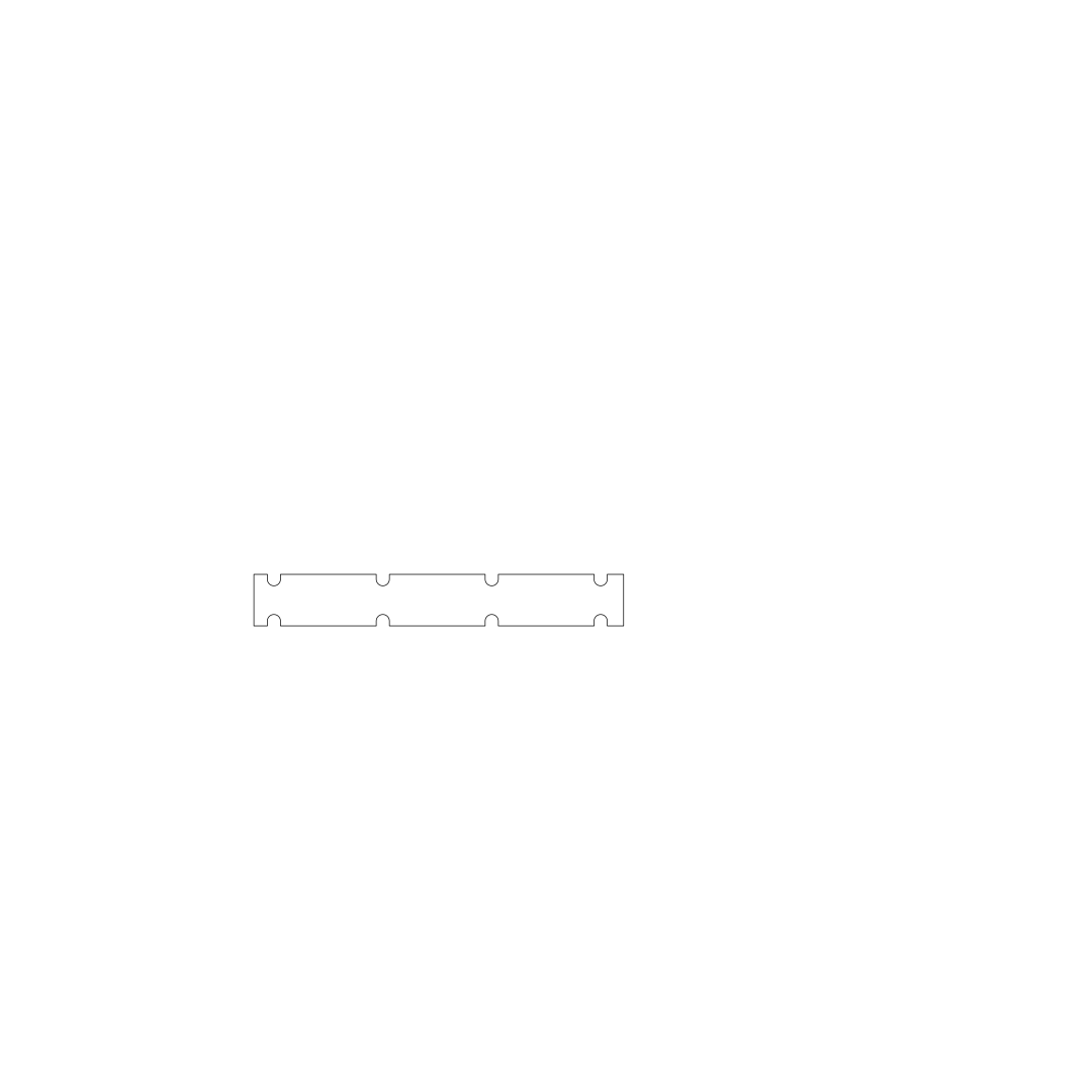
board_outline.svg
lekkelDefaultDebounce circuit for switches
Welcome to your new project. Imagine what you can build here.
Properties
Properties describe core aspects of the project.
Pricing & Availability
Distributor | Qty 1 |
|---|---|
Digi-Key | $0.18–$0.42 |
LCSC | $0.77 |
Mouser | $0.65 |
Controls
Welcome 👋
Flux helps you build PCBs faster with an AI teammate!
Create your account to collaborate, stay updated, fork your own version, and get instant answers from our AI agent.
singhrohan