Treat Flux like your intern. Tell it what you'd like to build and it'll get to work. You can also ask it questions, brainstorm ideas, and teach it your preferences. Learn More
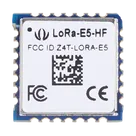
This project appears to be a LoRa-E5 transceiver module, which is an 868MHz/915MHz IoT module by Seeed Studio, featuring the STM32WLE5JC MCU, an ARM Cortex-M4 core-based SoC integrated with LoRa transceiver. This module is often used to build long-range wireless IoT networks.
The LoRa-E5 is popular in IoT applications due to their long-range communication capability, lower power consumption, and the secured LoRaWAN protocol.
The pins of the module are recognized as independent components in the project, which is why you have designators like PB15, PC0, GND, VCC, PB6, etc. These represent the various terminals or connection points on the LoRa-E5 module.
Here is a brief explanation of the pin designations:
PB, PC, PA prefixed designators correspond to the GPIO (General Purpose Input/Output) pins of the STM32 MCU, the numbering after the prefix is the GPIO number.
RST likely is the reset pin for the microcontroller.
RFIO likely represents RF input/output for the LoRa transceiver.
GND is the ground pin
VCC represents power supply
As of now, no electrical connections have been made in the project. You will need to establish these connections based on your circuit design requirements. Also, the project notes that all terminals are unspecified which means that you'll need to assign them as inputs or outputs based on your implementation.
2y
Someone is typing...
2
P1
PB15
PC0
GND
VCC
PB6
PB3
PB10
PB13
RST
GND
PB7
PB5
PA0
PB0
PB4
PA14
GND
GND
PC1
PA9
PA3
RFIO
PA2
PB14
PA15
PB9
PA10
PA13
No files yet
Reviews
Documents
Documents are markdown text files which describe project goals, capture details, or even simulation outputs.
ghoulflux
copilot
PB15,PC0,GND,VCC,PB6, etc. These represent the various terminals or connection points on the LoRa-E5 module.PB,PC,PAprefixed designators correspond to the GPIO (General Purpose Input/Output) pins of the STM32 MCU, the numbering after the prefix is the GPIO number.RSTlikely is the reset pin for the microcontroller.RFIOlikely represents RF input/output for the LoRa transceiver.GNDis the ground pinVCCrepresents power supply