Custom PCB Design Inquiry

I'm designing a battery-powered water level sensor for a residential
saltwater swimming pool. I have a working hardware concept but want
your recommendations on improvements, alternative parts, simplifications,
or a custom PCB design that integrates the modules.
================================================================
GOAL
Detect pool water level continuously, report via Home Assistant, and
trigger a Zigbee-controlled solenoid valve to top up evaporation losses.
Hard cutoff via independent float switch if the primary sensor fails open.
================================================================
HARD CONSTRAINTS (non-negotiable)
- Mounts entirely UNDER the pool skimmer lid. Skimmer is set into a concrete pool deck — no through-wall access. Lid is the only serviceable surface.
- Sensor sees the water surface from 13-20 cm (5-8 inches) above waterline, hanging vertically downward.
- Skimmer cavity is ~20 cm wide. Sensor beam angle should not bounce off cavity walls.
- Saltwater chlorine generator pool (~3000 ppm chloride). All wetted parts must be plastic — no stainless steel, no brass in contact with water/spray.
- Pool surface is 88-95°F, hot tub use. Ambient under-lid air is hot and condensing.
- Battery powered. Replaceable cell. Target ≥6 month life on a single 18650-class cell, ideally 1+ year.
- Two sensors with orthogonal physics (ultrasonic primary + mechanical float backstop) — single-sensor failures must not flood the pool.
- Integrates with Home Assistant. Already running ESPHome and Zigbee2MQTT on a Cauldron-HA instance.
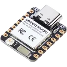
- MCU: Seeed XIAO ESP32-C6 (WiFi 6 + Thread + Zigbee + Matter, 15 µA deep sleep, ESPHome openthread component support, 21×17.5mm)
- Primary sensor: DFRobot A02YYUW (IP67 ultrasonic, 3-450cm range, 3cm blind zone, 60° beam, UART 9600, ESPHome a02yyuw component, 8mA active)
- Backstop: Madison M8000 vertical float switch (1/8" NPT, all-polypropylene stem and float, hermetically sealed reed switch, UL/CSA/NSF certified)
- Charger: TP5000 module set for LiFePO4 3.6V mode
- Battery: 18650 LiFePO4 1500mAh with integrated BMS
- Enclosure: 83×81×56mm IP67 ABS with M16 cable glands
- Refill plumbing: GiEX QT06 Zigbee solenoid valve with flow sensor + Watts 9D-M2 atmospheric backflow preventer
- Protection: silicone conformal coating on PCBs, indicating silica gel in enclosure, no resin potting (battery must remain replaceable)
- GPIO power-gating the ultrasonic sensor instead of a dedicated MOSFET (8 mA load << 40 mA GPIO limit on ESP32-C6)
- Float switch on GPIO with internal pull-up + delayed_on/off filtering for debounce, also serves as deep-sleep wake source
- 30-minute polling interval, only trust readings when pool pump has been off ≥10 minutes (water surface settling)
- HA-side automation handles refill logic; ESP only reports raw distance
- float state and acts on overfill cutoff
- WiFi day-one via ESPHome, with planned migration to Thread/openthread or Zigbee end-device firmware later for ~3× battery life
A) Recommend alternative parts where you see a better fit. Specifically:
- Is there a better ultrasonic, ToF, capacitive, or radar sensor for this geometry that I missed? (Note: ToF lasers ruled out due to condensation on optical windows. Through-wall mounting impossible.)
- Is there a better float switch with better saltwater resistance or smaller form factor than the Madison M8000?
- Better MCU for ultra-low-power Thread/Matter end devices? (I considered XIAO MG24 / Silicon Labs EFR32MG24 — 1.95 µA sleep — but ESPHome support is poor. If non-ESPHome firmware is acceptable for a 10× battery life win, recommend it.)
B) Design a custom PCB that integrates the XIAO carrier, TP5000 charge
circuit, USB-C power input, battery management, GPIO breakouts for
the ultrasonic and float switch with proper ESD protection, an LDO
or boost if needed, and test/programming pads. Goal: replace the loose
modules with one ~50×40mm board that mounts inside the IP67 enclosure.
C) Schematic-level recommendations for:
- ESD/TVS protection on external sensor lines (cables exit the enclosure)
- Reverse polarity protection on battery input
- Optional power-good LED that does not parasitically drain the cell
- Proper Thread/Matter antenna placement and ground plane considerations
- Low-Iq LDO recommendation if 3.3 V regulation is needed beyond what the XIAO provides
D) BOM with Mouser/DigiKey part numbers (NOT Amazon — production parts),
plus suggested PCB stackup and fab-house options (JLCPCB, OSHPark, PCBWay).
E) Identify any failure modes I haven't accounted for. Be specific —
"consider EMI" is useless; "the TP5000 switching at 1.2 MHz can couple
into the A02YYUW UART line if traces run parallel — recommend
minimum 5mm separation and ground pour between" is what I want.
Format the response as:
- Quick verdict on each starting-point part (keep / swap / consider)
- Recommended alternative parts with rationale
- Block diagram / schematic notes
- Custom PCB BOM with Mouser part numbers
- Top 3 risks I should design around
Thought
test
Thought