Q4 2022 Dogfooding - On Air
Daddy's second circuit board. A sign to let my wife know when I'm on a call. Activates with a slide switch and is powered by USB-C.... show more0 Uses
99 Comments
1 Star
Q4-2022-Dogfooding-On Air-markwu2001-Remix-R0
Modified by markwu2001: - Adjustable Brightness, - 85-90% Drive Efficiency - <5W Operation (Can use 5V 1A Plug) This project can be purchased from LCSC Original Description: Daddy's second circuit board. A sign to let my wife know when I'm on a call. Activates with a slide switch and is powered by USB-C.... show more0 Uses
28 Comments
1 Star
WiFi RF-ID lock reference design g7u8 eb3f 125c
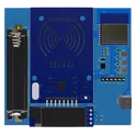
This project is a WiFi RF-ID Lock, which uses a Espressif ESP-8684 microcontroller for WiFi connectivity and a Handson Technology RC522 for RF-ID functionality. It also includes an OLED display and user control via a switch. A step-up power converter ensures consistent 3.3V power. #WiFi #MCU #ReferenceDesign #project #ESP8684 #lock #OLED #referenceDesign #simple-embedded #espressif #template #reference-design... show more0 Uses
27 Comments
1 Star
WiFi Door and Window Sensor
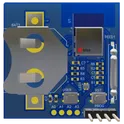
A compact battery-powered door/window sensor built around the ESP32-C3-MINI-1-N4 module. The design uses a single non-rechargeable AA cell with a TPS613221A 3.3 V boost regulator, reed switch magnetic contact sensing, low-power wake/report/sleep firmware strategy, RGB status LED for setup feedback, BOOT/EN controls, programming header, and input polarity protection. It is intended for smart-home security and automation applications, supporting WiFi or Bluetooth LE hub reporting with emphasis on low idle current, reliable RF burst power delivery, and field-replaceable battery operation. #ESP32-C3 #BLE #WiFi #DoorSensor #WindowSensor #ReedSwitch #LowPower #BatteryPowered #SmartHome #IoT... show more0 Uses
18 Comments
1 Star

Simple Delay Timer Circuit
This is a very simple timer circuit. When you push down to turn on the S1, this will turn on the LED and it also will charge the C1 Capacitor. Then upon releasing the push button switch, the LED will stay lit for couple of seconds until C1 is completely discharged.... show more0 Uses
11 Comments
1 Star
On Air R2 - Thread Enabled
R2 w Thread changes: -Moving to Letter Modules for ease of design -Adding MGM210L for Matter on Thread On/Off and intensity control -Shifted A and R letters closer to fix Kerning -Optional: Add unpopulated AA Battery Holder for battery option R1 changes: -Changed LED part to Red LEDs -adjusted resistor value of buck converter -Changed source for USB-C Connector -Removed exposed soldermask on buck converter with negative soldermask expansion -Order with black soldermask Modified by markwu2001: - Adjustable Brightness, - 85-90% Drive Efficiency - <5W Operation (Can use 5V 1A Plug) This project can be purchased from LCSC Original Description: Daddy's second circuit board. A sign to let my wife know when I'm on a call. Activates with a slide switch and is powered by USB-C. #template #arduino-matter... show more0 Uses
11 Comments
1 Star
BLE Door and Window Sensor Reference Design
This project is a BLE door and window sensor design that uses a U-blox BMD-330-A-R for BLE communication, a reed switch as a sensor, a multi-color LED for status display, and is powered by VBAT. There's also a programming interface and reset switch included. #WiFi #BLE #MCU #ReferenceDesign #project #referenceDesign #simple-embedded #ublox #template #reference-design... show more0 Uses
6 Comments
1 Star
WiFi RF-ID lock reference design vnb3
This project is a WiFi RF-ID Lock, which uses a Espressif ESP-8684 microcontroller for WiFi connectivity and a Handson Technology RC522 for RF-ID functionality. It also includes an OLED display and user control via a switch. A step-up power converter ensures consistent 3.3V power. #WiFi #MCU #ReferenceDesign #project #ESP8684 #lock #OLED #referenceDesign #simple-embedded #espressif #template #reference-design... show more0 Uses
1 Comment
1 Star
push-on-hold-off
A power switch using a push button. It turns on with a single press and only turns off when you hold the button down. This could be used to get functionality similar to most laptops where a single press when on will initiate a "soft" shutdown but you can force a "hard" shutdown by holding it down.... show more0 Uses
1 Comment
1 Star
BLE Encoder New LED
BLE remote control board. Based on SoC ESP32-C3-MINI-1 that allows you to program it as HID volume multichannel control, you can switch channels with the user button, or use it as arrow keys.... show more0 Uses
1 Comment
1 Star
CheckIt_mini
CheckIt is a daily habit tool. When you complete a habit, flip a switch, then an LED lights up. Future work will include wiring the 24pin FPC port to the Pico which causes an e-paper screen to display a message when a switch is flipped. This PCB runs using a Raspberry Pi Pico and has plans to be battery powered similar to a digital alarm clock.... show more0 Uses
1 Comment
1 Star
Trace Chamfers
This circuit drives 10 LEDs making them flash to the rhythm of the music (using a TIP31C transistor to act as a voltage-controlled switch) Credit: https://www.youtube.com/watch?v=3qZ3uA8hDmE... show more0 Uses
1 Comment
1 Star
CH340N SerialUPDI Programmer
Simple UPDI programmer for tinyAVR, megaAVR and AVR-Dx microcontrollers with voltage selection switch (5V and 3.3V).... show more0 Uses
1 Comment
1 Star
BLE Encoder
BLE remote control board. Based on SoC ESP32-C3-MINI-1 that allows you to program it as HID volume multichannel control, you can switch channels with the user button, or use it as arrow keys.... show more0 Uses
1 Comment
1 Star
LiftLink Boat Lift Controller
Outdoor ESP32-based 12/24 V boat-lift controller with isolated ShoreStation switch emulation, ultrasonic height sensing, battery monitoring, and protected canopy-light control.... show more0 Uses
0 Comments
1 Star
ThirstIQ Cap
High-level recreation of the ThirstIQ Cap wiring diagram using an ESP32-WROOM-32 with AMS1117-3.3 regulated battery input, inline ON/OFF switch, four touch input headers on IO32/IO33/IO25/IO26, shared I2C OLED and RTC on IO21/IO22, UART debug/programming header on TXD0/RXD0, BOOT and RESET pushbuttons on IO0 and EN, buzzer on IO4, common 3V3/GND distribution, and PCB preparation for a 160 mm x 100 mm 4-layer layout. Layout intent includes clean 3.3 V power distribution, local decoupling for regulator and ESP32, accessible external headers/buttons, short clean BOOT/EN traces, shared I2C routing, touch-signal separation from noisy power and buzzer traces, and ESP32 antenna keepout.... show more0 Uses
0 Comments
1 Star
Realistic Brown Battle Mech
Nice — you can do a clean pulse + latch using a single quad Schmitt-NAND chip: 74HC132 (or 74LVC132 for 3.3 V systems). The HC132 contains four 2-input NAND gates with Schmitt inputs so you can both clean a noisy SYN480R DATA line and build an SR latch (NAND SR is active-LOW) inside one package. Only a few passives and a driver transistor are needed. Below is a ready-to-build recipe (parts, wiring, explanation, tuning tips, and an ASCII schematic) — no extra logic ICs required. Parts (per latch) 1 × 74HC132 (quad 2-input NAND with Schmitt inputs). If your system is 3.3 V use 74LVC132 / 74HC132 rated for 3.3 V. Rin = 47 kΩ (input series) Cfilter = 10 nF (input RC to ground) — tweak for debounce/clean time Rpulldown = 100 kΩ (pull-down at input node, optional) Rpullup = 100 kΩ (pull-up for active-LOW R input so reset is idle HIGH) Rbase = 10 kΩ, Q = 2N2222 (NPN) or small N-MOSFET (2N7002) to drive your load Diode for relay flyback (1N4001) if you drive a coil Optional small cap 0.1 µF decoupling at VCC of IC Concept / how it works (short) Use Gate1 (G1) of 74HC132 as a Schmitt inverter by tying its two inputs together and feeding a small RC filter from SYN480R.DATA. This removes HF noise and provides a clean logic transition. Because it's a NAND with tied inputs its function becomes an inverter with Schmitt behavior. Use G2 & G3 as the cross-coupled NAND pair forming an SR latch (active-LOW inputs S̄ and R̄). A low on S̄ sets Q = HIGH. A low on R̄ resets Q = LOW. Wire the cleaned/inverted output of G1 to S̄. A valid received pulse (DATA high) produces a clean LOW on S̄ (because G1 inverts), setting the latch reliably even if the pulse is brief. R̄ is your reset input (pushbutton, HT12D VT, MCU line, etc.) — idle pulled HIGH. Q drives an NPN/MOSFET to switch your load (relay, LED, etc.). Recommended wiring (pin mapping, assume one chip; use datasheet pin numbers) I’ll refer to the 4 gates as G1, G2, G3, G4. Use G4 optionally for additional conditioning or to build a toggler later. SYN480R.DATA --- Rin (47k) ---+--- Node A ---||--- Cfilter (10nF) --- GND | Rpulldown (100k) --- GND (optional, keeps node low) Node A -> both inputs of G1 (tie inputs A and B of Gate1 together) G1 output -> S̄ (S_bar) (input1 of Gate2) Gate2 (G2): inputs = S̄ and Q̄ -> output = Q Gate3 (G3): inputs = R̄ and Q -> output = Q̄ R̄ --- Rpullup (100k) --- VCC (reset is idle HIGH; pull low to reset) (optional) R̄ can be wired to a reset pushbutton to GND or to an MCU pin Q -> Rbase (10k) -> base of 2N2222 (emitter GND; collector to one side of relay coil) Other side of relay coil -> +V (appropriate coil voltage) Diode across coil If you prefer MOSFET low side switching: Q -> gate resistor 100Ω -> gate of 2N7002 2N7002 source -> GND ; drain -> relay coil low side... show more0 Uses
0 Comments
1 Star
Fast Silver Flubber
Create a schematic diagram of an electric fence controller using the NE556 dual timer IC. The circuit must include all components with clear electronic symbols (resistors, capacitors, transistors, diode, relay) connected by lines as in a real circuit diagram. Specifications: 1. Power supply: - Vcc = +12V connected to pin 14 of the NE556. - Pin 1 of the NE556 to ground. 2. Timer A (active 10 seconds): - Pin 2 (Trigger A) receives a pulse from transistor Q2 (contact detector). - Pin 6 (Threshold A) connected to Pin 7 (Discharge A). - R1 = 1 MΩ between Pin 7 and +12V. - C1 = 10 µF between Pin 6 and ground. - Pin 3 (Out A) goes through a 4.7 kΩ resistor to the base of Q1 (BC547 NPN transistor). - Pin 3 also connected via a 100 nF capacitor to Pin 13 (Trigger B of Timer B). 3. Timer B (rest 10 seconds): - Pin 9 (Discharge B) and Pin 8 (Threshold B) connected together. - R2 = 1 MΩ between Pin 9 and +12V. - C2 = 10 µF between Pin 8 and ground. - Pin 12 (Out B) can be optionally used to block retrigger of Timer A. 4. Relay driver stage: - Q1 = BC547 NPN transistor. - Base connected through 4.7 kΩ resistor to Pin 3 (Out A). - Emitter to ground. - Collector connected to one side of the relay coil. - Other side of relay coil connected to +12V. - A diode 1N4007 placed in parallel with the relay coil (cathode to +12V, anode to collector of Q1). - Relay contacts switch the +12V supply to the electric fence energizer. 5. Contact detector: - Shunt resistor ≈0.1 Ω placed in series with the fence output. - Q2 = BC547 NPN transistor, base connected to the shunt, emitter to ground, collector to Pin 2 (Trigger A). - When current flows through the shunt, Q2 provides a trigger pulse to Timer A. Please draw the schematic in a standard style with components connected by straight lines, not in block diagrams. Show clear pin numbers of the NE556 and all external components.... show more0 Uses
0 Comments
1 Star
WiFi RF-ID lock reference design g7u8 eb3f
This project is a WiFi RF-ID Lock, which uses a Espressif ESP-8684 microcontroller for WiFi connectivity and a Handson Technology RC522 for RF-ID functionality. It also includes an OLED display and user control via a switch. A step-up power converter ensures consistent 3.3V power. #WiFi #MCU #ReferenceDesign #project #ESP8684 #lock #OLED #referenceDesign #simple-embedded #espressif #template #reference-design... show more0 Uses
0 Comments
1 Star

Brkrbox V0
Flatbox styled hand solderable PCB featuring a side passthrough, oled screen, focus mode and DP/LS/RS switch... show more0 Uses
0 Comments
1 Star
test Music LED 3GFe
This circuit drives 10 LEDs making them flash to the rhythm of the music (using a TIP31C transistor to act as a voltage-controlled switch) Credit: https://www.youtube.com/watch?v=3qZ3uA8hDmE... show more0 Uses
0 Comments
1 Star
On Air-markwu2001-Remix-R1 Backup Freeze
R1 changes: -Changed LED part to Red LEDs -adjusted resistor value of buck converter -Changed source for USB-C Connector -Removed exposed soldermask on buck converter with negative soldermask expansion -Order with black soldermask Modified by markwu2001: - Adjustable Brightness, - 85-90% Drive Efficiency - <5W Operation (Can use 5V 1A Plug) This project can be purchased from LCSC Original Description: Daddy's second circuit board. A sign to let my wife know when I'm on a call. Activates with a slide switch and is powered by USB-C.... show more0 Uses
0 Comments
1 Star
Arduino 220v Switching
Welcome to your new project. Imagine what you can build here.... show more0 Uses
0 Comments
1 Star
Arduino Force Units Connection Shield
An I2C extension shield with 6 shielded ethernet ports and a TCA9548 breakout board. This board is for the target side, any microcontroller with a standard Arduino header can use it. With proper target side hardware and an SSTP ethernet cable, the board provides robust i2c communication over 10ft(could be longer, haven't tested it yet) with a bitrate of 400kHz under a noisy environment( near motors, power cables, switches, etc). The shield board provides power to the target side and can power the i2c device. The board also supports drdy trigger, which is available on many i2c sensors. The TCA9548 breakout board is for a scenario in which all of your i2c devices have the same address. #Arduino #Uno #Shield #Template #project-template #project... show more0 Uses
45 Comments
1 Star