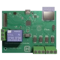
PICO Smart Automation Controller NextPCB 1-4 Layer Standard Constraints 4zrx 4be4 i7TP
Use this template if you plan to get your 1-4 layer boards manufactured with HQ NextPCB (nextpcb.com). This template is designed for generic designs to minimize unnecessary costs and complications where possible. https://www.nextpcb.com/pcb-capabilities #project-template #template #manufacturer-design-rules... show more0 Uses
0 Comments
0 Stars
PICO Smart Automation Controller NextPCB 1-4 Layer Standard Constraints 4zrx 4be4 uttt
Use this template if you plan to get your 1-4 layer boards manufactured with HQ NextPCB (nextpcb.com). This template is designed for generic designs to minimize unnecessary costs and complications where possible. https://www.nextpcb.com/pcb-capabilities #project-template #template #manufacturer-design-rules... show more0 Uses
0 Comments
0 Stars
PICO Smart Automation Controller NextPCB 1-4 Layer Standard Constraints 4zrx 4be4 xoAh
Use this template if you plan to get your 1-4 layer boards manufactured with HQ NextPCB (nextpcb.com). This template is designed for generic designs to minimize unnecessary costs and complications where possible. https://www.nextpcb.com/pcb-capabilities #project-template #template #manufacturer-design-rules... show more0 Uses
0 Comments
0 Stars
PICO Smart Automation Controller NextPCB 1-4 Layer Standard Constraints 4zrx 4be4 s8ha
Use this template if you plan to get your 1-4 layer boards manufactured with HQ NextPCB (nextpcb.com). This template is designed for generic designs to minimize unnecessary costs and complications where possible. https://www.nextpcb.com/pcb-capabilities #project-template #template #manufacturer-design-rules... show more0 Uses
0 Comments
0 Stars
PICO Smart Automation Controller NextPCB 1-4 Layer Standard Constraints 4zrx 4be4 o5jM
Use this template if you plan to get your 1-4 layer boards manufactured with HQ NextPCB (nextpcb.com). This template is designed for generic designs to minimize unnecessary costs and complications where possible. https://www.nextpcb.com/pcb-capabilities #project-template #template #manufacturer-design-rules... show more0 Uses
0 Comments
0 Stars
PICO Smart Automation Controller NextPCB 1-4 Layer Standard Constraints 4zrx 4be4
Use this template if you plan to get your 1-4 layer boards manufactured with HQ NextPCB (nextpcb.com). This template is designed for generic designs to minimize unnecessary costs and complications where possible. https://www.nextpcb.com/pcb-capabilities #project-template #template #manufacturer-design-rules... show more0 Uses
0 Comments
0 Stars
PICO Smart Automation Controller NextPCB 1-4 Layer Standard Constraints 4zrx 4be4
Use this template if you plan to get your 1-4 layer boards manufactured with HQ NextPCB (nextpcb.com). This template is designed for generic designs to minimize unnecessary costs and complications where possible. https://www.nextpcb.com/pcb-capabilities #project-template #template #manufacturer-design-rules... show more0 Uses
0 Comments
0 Stars

55% Quotex Promo Code: Shipthedeal
55% Free Quotex Promo and Bonus Code: shipthedeal Looking to start trading with a little extra cushion? This guide explains how the 55% free Quotex promo works, how to use the bonus code: shipthedeal, and what to check before you deposit so you know exactly what you’re getting. Quick summary (what you get) Promo: Up to 55% bonus (typically applied to an eligible deposit) Code: shipthedeal Best for: New users or anyone planning a deposit who wants added starting balance Important: Bonuses often come with terms (like minimum deposit, eligible payment methods, and withdrawal/turnover conditions) How to claim the 55% promo with code shipthedeal Sign in to your Quotex account (or create one if you’re new). Go to the Deposit / Payments section. Look for a field like “Promo code”, “Bonus code”, or “Coupon code.” Enter: shipthedeal Select your deposit amount and complete the payment. Confirm the bonus appears in your balance/transaction details. If the bonus doesn’t apply, skip to the troubleshooting section below. How the 55% bonus usually works (plain English) A deposit bonus generally adds extra trading credit on top of your deposit. For example, if the promo applies at 55%, a qualifying deposit can increase your starting balance by an additional amount. The exact calculation and eligibility rules can vary by region, payment method, or account status—so always check the promo description in your account before funding. What to check before using any promo code (so there are no surprises) Promotions commonly come with rules. Before you commit, review: Minimum deposit required to activate the 55% offer Eligible payment methods (some methods don’t qualify for bonus promos) Whether the bonus is withdrawable or is “trading credit” only Turnover/volume requirements before withdrawals (if any) Expiry window (some codes are time-limited) Country/region restrictions Troubleshooting: code shipthedeal not working? Try these quick fixes: Double-check spelling/case: shipthedeal (no spaces) Switch payment method: some promos only work on certain rails Check if you already have a different promo active: platforms often allow only one active bonus at a time Try a different deposit amount: some bonuses only trigger above a threshold Look for the “Apply bonus” toggle: sometimes you must manually enable the bonus on the deposit screen If none of those work, the most likely reasons are regional restrictions, promo expiration, or ineligibility for the specific account. Should you use a deposit bonus? A bonus can be useful if: You’re already planning to deposit and want extra starting balance You understand any withdrawal/volume conditions attached to the bonus You may want to skip it if: You want maximum flexibility to withdraw quickly The promo’s terms aren’t clear in your account FAQ Is shipthedeal a free bonus with no deposit? Usually, a “55% bonus code” is a deposit-related promotion. If there’s a no-deposit offer, it’s typically labeled explicitly as such inside the platform. Can I withdraw the bonus immediately? Often no—many bonuses require certain activity conditions first. Check the offer terms shown during deposit. Can I use shipthedeal more than once? Commonly it’s one-time per user or limited-use, but this depends on the promo rules shown in your account.... show more0 Uses
0 Comments
0 Stars
crobo-referral-code-1a19gbih
Crobo Referral Code: 1a19gbih If you are looking for the Crobo referral code to start sending money to India with extra rewards, you can use the code 1a19gbih during signup. Crobo is a fast-growing international money transfer app created by experienced ex-Amazon engineers, designed to make remittances simple, affordable, and transparent. With competitive exchange rates and instant transfers, Crobo offers a modern alternative to traditional money transfer services. Using the Crobo referral code when you create your account unlocks a special reward. After you complete your first successful transfer, both you and the person who referred you can receive a $25 Amazon Gift Card. This referral program makes Crobo attractive for people who regularly send money abroad while also helping friends benefit from the platform. One of the major advantages of Crobo is its $0 transaction fee policy. Many international transfer services charge hidden processing or service fees, but Crobo focuses on keeping transfers affordable. Combined with excellent exchange rates, this means that more of your money reaches your family or recipient in India instead of being lost to fees. Another key benefit is speed. Crobo is designed for fast digital remittances, allowing users to send funds from the United States to India quickly and securely. The app’s streamlined interface makes the process simple: create an account, verify your details, add your recipient, and send money within minutes. To get started, simply sign up using the link below and enter the Crobo referral code during registration: By applying the Crobo referral code, you unlock the referral reward and can start transferring money with better rates, no transaction fees, and a smooth digital experience. If you regularly send money to India, Crobo can be a convenient solution that combines reliability, speed, and user rewards in one platform.... show more0 Uses
0 Comments
0 Stars
Single Lead Heart Rate Monitor - AD8232
Use this template if you're planning to get your 1 to 2-layer board manufactured in JLCPCB. It has the via min/max and trace width constraints already baked as global rules. #project-template... show more0 Uses
0 Comments
0 Stars
Photon-2-reference-design
Use this template if you're planning to get your 1 to 2-layer board manufactured in JLCPCB. It has the via min/max and trace width constraints already baked as global rules. #project-template #template... show more0 Uses
0 Comments
0 Stars
CONfirmeD*] TEMU CoupoN Code 40 Off [ACX420275] For First Time Users
New users at Temu receive a 40% Off discount on orders over 40% Off Use the code ["acx420275" or "acr841270"] during checkout to get Temu Discount 40% off For New Users. You can save 40% Off off your first order with the Promo Code available for a limited time only. Extra 30% off for new and existing customers + Up to $40 Off % off & more. Temu Promo Codes for New users-["ACX420275" or "acx420275"] Temu discount code for New customers- ["ACX420275" or "acx420275"] Temu $40 Off Promo Code- ["ACX420275" or "acx420275"] what are Temu codes- "ACX420275" or "acx420275" does Temu give you $40 Off - ["ACX420275" or "acx420275"] Yes Verified Temu New customer offer {"ACX420275" or "acx420275"} Temu discount code 2026 {"ACX420275" or "acx420275"} 100 off Promo Code Temu {"ACX420275" or "acx420275"} Temu 100% off any order {"ACX420275" or "acx420275"} 100 dollar off Temu code {"ACX420275" or "acx420275"} Temu coupon $40 Off off for New customers There are a number of discounts and deals shoppers n take advantage of with the Teemu Coupon Bundle ["ACX420275" or "acx420275"]. Temu coupon $40 Off off for New customers ["ACX420275" or "acx420275"] will save you $40 Off on your order. To get a discount, click on the item to purchase and enter the code. You n think of it as a supercharged savings pack for all your shopping needs Temu Promo Code 80% off – ["ACX420275" or "acx420275"] Free Temu codes 50% off – ["ACX420275" or "acx420275"] Temu coupon $40 Off off – ["ACX420275" or "acx420275"] Temu buy to get ₱39 – ["ACX420275" or "acx420275"] Yes, Temu offers 40% off coupon code [{"acx420275" or "acr841270"}] for first-time users. You can get a $40 bonus plus 40% off any purchase at Temu with the $100 Coupon Bundle if you sign up with the referral code ["ACX420275" or "acx420275"] and make a first purchase of $100 or more. The Temu 40% Off coupon code ("acx420275" or "acr841270") will save you 40% on your order. To get a discount, click on the item to purchase and enter the code. Yes Temu offers 40% Off Coupon Code "acx420275" or "acr841270” for Existing Customers. You can get a 40% discount with Temu coupon code {"acx420275" or "acr841270"}. This exclusive offer is for existing customers and can be used for a 40% reduction on your total purchase. Enter coupon code {“acx420275" or "acr841270"} at checkout to avail of the discount. You can use the code {"acx420275" or "acr841270"} to get a 40% off Temu coupon as a new customer. Apply this Temu coupon code 40% off "acx420275" to get a 40% discount on your shopping with Temu. If you are who wish to join Temu, then you should use this exclusive Temu coupon code 40% off ("acx420275") and get 40% off on your purchase with Temu. * "ACX420275" or "acx420275": Enjoy flat 40% off on your first Temu order. * "ACX420275" or "acx420275": Download the Temu app and get an additional 40% off. * "ACX420275" or "acx420275": Celebrate spring with up to 90% discount on selected items. * "ACX420275" or "acx420275": Score up to 90% off on clearance items. * "ACX420275" or "acx420275": Beat the heat with hot summer savings of up to 90% off. * "ACX420275" or "acx420275": Temu UK Coupon Code to 40% off on Appliances at Temu. Temu Promo Code 80% off – ["ACX420275" or "acx420275"] Free Temu codes 50% off – ["ACX420275" or "acx420275"] Temu coupon $40 Off off – ["ACX420275" or "acx420275"] Temu buy to get ₱39 – ["ACX420275" or "acx420275"] Temu 129 coupon bundle – ["ACX420275" or "acx420275"] Temu buy 3 to get €99 – ["ACX420275" or "acx420275"] Exclusive $40 Off Off Temu Discount Code Temu $40 Off Off Promo Code : "ACX420275" or "acx420275" Temu Discount Code $40 Off Bundle ("ACX420275" or "acx420275") "ACX420275" or "acx420275" Temu $40 Off off Promo Code for Existing users : ("ACX420275" or "acx420275") Temu Promo Code $40 Off off Verified user can get a 40 off Temu Coupon code using the code ((acx420275”)). This Temu 40 Off code is specifically for new and existing customers both and can be redeemed to receive a 40 discount on your purchase. Our exclusive Temu Coupon code offers a flat 40 off your purchase, plus an additional 30% discount on top of that. You can slash prices by up to 40 as a new Temu customer using code ((acx420275”)). Existing users can enjoy 40 off their next haul with this code. But that’s not all! With our Temu Coupon codes for 2025, you can get up to 90% discount on select items and clearance sales. Whether you’re a new customer or an existing shopper, our Temu codes provide extra discounts tailored just for you. Save up to 30% with these current Temu Coupons ["^"acx420275"^"] for October 2025. The latest Temu Coupon codes at here.... show more0 Uses
0 Comments
0 Stars
PCB Xpress - Standard Board
PCB Xpress Standard Manufacturing Specs Supported Layers: 1, 2, 4, 6, 8 (up to 32) Material: FR4, Isola, Rogers Soldermask Colors: Green, Red, White Silkscreen/Legend: White, Black Surface Finish: HASL, ENIG, OSP Copper Thickness: 18µm (0.5oz), 25µm, 35µm (1oz), 70µm (2oz) Min Copper: 1.4 micron Instructions for AI Copilot: If the user asks for a board, default to 2 Layers, FR4, Green Mask, White Legend, HASL finish. Ensure the board shape is rectangular if possible (Width/Height in mm). Need more layers? Just ask Copilot: '@copilot change this board to 4 layers'.... show more0 Uses
0 Comments
0 Stars
Inherent Crimson Transporter
SmartDeskPet v1.0 Shield Stage 1 status: - Goal: 5V input -> dual AMS1117-3.3 rails (+3V3_MCU and +3V3_WIFI) with common GND. - Note: Keep power nets explicitly named (avoid unnamed nets) to keep ERC happy. Stage 1 completion checklist: - Mark J1 Pin_1 (+5V) as a Power Output pin to satisfy ERC power-driver checks. - Verify all GND symbols/returns are on the same GND net. - Keep +5V_SERVO isolated from the main +5V net (only share GND). Stage 2 preparation notes (MPN/LCSC + layout constraints): - MPN/LCSC targets to define before Stage 2 exit: - AMS1117-3.3 (SOT-223): set exact MPN and (optionally) LCSC PN for both U1 and U2. - 100nF capacitor (0603): set MPN/LCSC for all 0603 100nF decouplers. - 4.7k resistor (0603): set MPN/LCSC for I2C pull-ups R1 and R2. - 1000uF bulk capacitor (radial): set MPN/LCSC for C7 (CP_Radial_D10.0mm_P5.00mm). - DC005 power jack/regulator input: select exact DC005 footprint + MPN/LCSC (if used). - 2.54mm headers/sockets: set MPN/LCSC for H1, H2, J1, J3, J4, J5, P3, P4, P5, and J2. - ESP-01S antenna keepout: - Reserve a copper keepout under and in front of the ESP-01S onboard antenna. - No copper pours/traces/components in the antenna region (top and bottom) per module guidelines. - H1/H2 header spacing: - Maintain 1000 mil spacing between H1 and H2 header centerlines (shield mechanical requirement). - Silkscreen placeholders: - Add silkscreen labels for: 5V IN, GND, +3V3_MCU, +3V3_WIFI, SERVO1, SERVO2, I2C SDA/SCL, DHT11, ASRPRO UART2, ESP-01S UART3. - Add placeholder text for: MPN, LCSC, board revision, and date code. Stage 3 layout constraints (placement and routing guidance): - Connector placement strategy: - Place H1 and H2 first to lock the shield mechanical interface; enforce 1000 mil spacing. - Place J1 and any DC005 input at the board edge for easy access. - Designated power area planning: - Group U1, U2, and C7 near the 5V entry point; keep high-current 5V and regulator loops short. - Use wide copper for +5V and any servo supply; stitch GND around power section. - Antenna keepout boundaries: - Place J2 (ESP-01S socket) at a board edge with the antenna facing outward. - Enforce a top-and-bottom copper keepout in the antenna region; keep noisy power traces away.... show more0 Uses
0 Comments
0 Stars
PICO Smart Automation Controller [Prod_V1_AUTO_NET_CLASS_12-10]
Use this template if you plan to get your 1-4 layer boards manufactured with HQ NextPCB (nextpcb.com). This template is designed for generic designs to minimize unnecessary costs and complications where possible. https://www.nextpcb.com/pcb-capabilities #project-template #template #manufacturer-design-rules... show more0 Uses
0 Comments
0 Stars
RedotPay Referral Code: i88n3
RedotPay Referral Code: i88n3 Earn Up to 40% Commission & Crypto Rewards If you’re looking for the best and most updated RedotPay Referral Code, use i88n3 to get instant rewards when you sign up through the official link: 👉 Download now... show more0 Uses
0 Comments
0 Stars
Times Prime Referral Code: A87R0S0F
If you’re searching for a working Times Prime Referral Code, use A87R0S0F to get up to ₹1000 OFF instantly on your Times Prime membership.... show more0 Uses
0 Comments
0 Stars
Active Three-Way Crossover on NE5532
TECHNICAL ASSIGNMENT AND DESIGN GUIDE Active Three-Way Crossover on NE5532 Powered by AM4T-4815DZ and Amplifiers TPA3255 (Updated Version) 1. GENERAL PURPOSE OF THE DEVICE The goal of the development is to create an active three-way audio crossover for one channel of a loudspeaker system, working with the following drivers: LF: VISATON W250 MF: VISATON MR130 HF: Morel MDT-12 Each frequency range is amplified by a separate power amplifier: LF: TPA3255 in PBTL mode (mono) MF + HF: second TPA3255 in stereo mode (one channel for MF, the other for HF) The crossover accepts a single linear audio signal (mono) and divides it into three frequency bands: Range Frequency Range LF 0 – 650 Hz MF 650 – 2500 Hz HF 2500 Hz and above Filter type: Linkwitz–Riley 4th order (24 dB/oct) at each crossover point (650 Hz and 2500 Hz). The crossover must provide: minimal self-noise; no audible distortion in the audible range; stable operation with NE5532 at ±15 V power supply; easy adjustment of the level for each band, as well as the overall level (via the input buffer). 2. FILTER TYPES AND BASIC OPERATING PRINCIPLES Each filter is implemented as two cascaded Sallen–Key 2nd order (Butterworth) stages, resulting in a final 4th order LR4 filter. Topology: non-inverting Sallen–Key, optimal for NE5532. For all stages: Cascade gain: K ≈ 1.586 This provides a Q factor of 0.707 (Butterworth), which in combination gives a Linkwitz–Riley 4th order. 3. COMPONENT VALUES FOR FILTERS 3.1 Universal Parameters RC chain capacitors: 10 nF, film capacitors, tolerance ≤ 5% Resistors: metal-film, tolerance ≤ 1% The gain of each stage is set by feedback resistors: Rf = 5.9 kΩ Rg = 10 kΩ K ≈ 1 + (Rf / Rg) ≈ 1.59 The circuit should allow for the installation of a small capacitor (10–47 pF) in parallel with Rf (footprint provided) for possible stability correction (not mandatory to install in the first revision). 3.2 650 Hz Filters (Low-frequency boundary for MF) These are used for the division between W250 and MR130. LP650 — Low-frequency Filter 2nd Order R1 = 24.9 kΩ R2 = 24.9 kΩ C1 = 10 nF C2 = 10 nF Two stages: LP650 #1 and LP650 #2. HP650 — MF High-frequency Filter 2nd Order Same values: R1 = 24.9 kΩ R2 = 24.9 kΩ C1 = 10 nF C2 = 10 nF Two stages: HP650 #1 and HP650 #2. 3.3 2500 Hz Filters (Upper boundary for MF) These are used for the division between MR130 → MDT-12. LP2500 — High-pass MF Filter R1 = 6.34 kΩ R2 = 6.34 kΩ C1 = 10 nF C2 = 10 nF Two stages: LP2500 #1 and LP2500 #2. HP2500 — High-frequency Filter Same values: R1 = 6.34 kΩ R2 = 6.34 kΩ C1 = 10 nF C2 = 10 nF Two stages: HP2500 #1 and HP2500 #2. 4. OPERATIONAL AMPLIFIERS The NE5532 (dual op-amp, DIP-8 or SOIC-8) is used. A minimum of 4 packages (8 channels) for filters: NE5532 Function U1A, U1B LP650 #1, LP650 #2 (LF) U2A, U2B HP650 #1, HP650 #2 (Lower MF cut-off) U3A, U3B LP2500 #1, LP2500 #2 (Upper MF cut-off) U4A, U4B HP2500 #1, HP2500 #2 (HF) Additionally: U5 — input buffer / preamplifier (both channels) If necessary, an additional NE5532 (U6) for the balanced input (see section 6.2). All NE5532 should have local decoupling for power supply (see section 5.1). 5. CROSSOVER POWER SUPPLY AM4T-4815DZ DC/DC module is used: Input: 36–72 V, connected to the 48 V power supply for TPA3255 amplifiers. Output: +15 V / –15 V, up to 0.133 A per side. Maximum output capacitance: ≤ 47 µF per side (according to the datasheet). 5.1 Power Filtering Input (48 V): RC variant (simpler, acceptable for the first revision): R = 1–2 Ω / 1–2 W C = 47–100 µF (for 63 V or higher) LC variant (preferred for improved noise immunity): L = 10–22 µH C = 47–100 µF The developer may implement LC if confident in choosing the inductance and its parameters. Output +15 V and –15 V (general filtering): Electrolytic capacitor 10–22 µF per side 100 nF (X7R) per side to GND Local decoupling for NE5532 (REQUIRED): For each NE5532 package: 100 nF between +15 V and GND 100 nF between –15 V and GND Place as close as possible to the op-amp power pins (short traces). Additional local filtering for power lines: For each NE5532, decouple from the ±15 V main rails: Either 4.7–10 Ω resistor in series with +15 V and –15 V, Or ferrite bead in each rail. After this component, place local capacitors (100 nF + 1–4.7 µF) to ground. 6. INPUT TRACT: INPUTS, BUFFER, ADJUSTMENT 6.1 Unbalanced Input (RCA / Jack / Linear) The main mode is the unbalanced linear input, for example, RCA. Input tract structure: RF-filter and protection: Signal → series resistor Rin_series = 100–220 Ω After resistor — capacitor Cin_RF = 470–1000 pF to GND This forms a low-level RF filter and reduces high-frequency noise. DC-block (low-pass HP-filter): Capacitor Cin_DC = 2.2–4.7 µF film in series Resistor to ground Rin_to_GND = 47–100 kΩ Cut-off frequency — negligible in the audio range but removes DC. Input buffer / preamplifier (NE5532, U5): Non-inverting configuration. Input — after DC-block. Gain: adjustable, e.g., Rg_fixed = 10 kΩ (to GND through trimmer) Rf = 10–20 kΩ + footprint for trimmer (e.g., 20 kΩ) The gain should be in the range of 0 dB to +10…+12 dB. Possible configuration: Rg = 10 kΩ fixed Rf = 10 kΩ + 10 kΩ trimmer in series. This allows adjusting the overall level of the crossover according to the source and amplifier levels. Buffer output: A low-impedance output (after NE5532) This signal is simultaneously fed to the inputs of all filters: LP650 (LF) HP650 → LP2500 (MF) HP2500 (HF) 6.2 Balanced Input (XLR / TRS) — Optional, but laid out on the board The board should allow for a balanced input, even if it’s not used in the first revision. Implementation requirements: XLR/TRS connector (L, R, GND) or separate 3-pin header. Simple differential receiver on NE5532 (extra U6 package or use one channel of U5 if sufficient). Circuit: classic instrumentation amplifier or differential amplifier: Inputs: IN+ and IN– Output — single-ended signal of the same level (or slightly amplified), fed to DC-block and buffer (or directly to the buffer if integrated). Switching between balanced/unbalanced mode: Implement using jumpers / bridges or adapters: Either switch before the buffer, Or use two separate pads, one of which is unused. All balanced input grounds must be connected to the same AGND point as the unbalanced input to avoid ground loops. 7. LEVEL ADJUSTMENT OF BANDS (BEST METHOD) The level adjustment of each band (LOW, MID, HIGH) is required to match the sensitivity of the speakers and amplifiers. Recommended method: After each full filter (after LP650×2, MID-chain HP650×2 → LP2500×2, HP2500×2), install: A passive attenuator: Series: Rseries (0–10 kΩ, adjustable) Shunt: Rshunt to GND (10–22 kΩ, fixed or adjustable) For simplicity and reliability: Implementation on the board: For each band (LOW, MID, HIGH) provide: Pad for multi-turn trimmer 10–20 kΩ as a divider (between signal and ground) in the "level adjustment" configuration. If adjustment is not needed — install a fixed divider (two resistors) or simply use a jumper. It is preferable to use: For setup: multi-turn trimmers 10–20 kΩ, available on the top side of the board. Nominals for the initial configuration can be selected through measurements, but the PCB should have flexibility. This provides: Accurate balancing of band volumes without interfering with the filters; Flexibility for fine-tuning to the specific characteristics of the speakers. 8. INPUTS AND OUTPUTS OF THE CROSSOVER (FINAL) 8.1 Inputs 1× Unbalanced linear input (RCA or 3-pin header) 1× Balanced input (XLR/TRS or 3-pin header) — optional, but space must be provided on the board. Input impedance (unbalanced after RF-filter): 22–50 kΩ. The input tract must be implemented using shielded cables. 8.2 Outputs Outputs to amplifiers: Output Signal LOW OUT After LP650×2 (LF) MID OUT After HP650×2 → LP2500×2 (MF) HIGH OUT After HP2500×2 (HF) Each output: Series resistor 100–220 Ω (prevents possible oscillations and simplifies cable management). A nearby own AGND pad (ground output), so the signal pair SIG+GND runs together. Outputs should be compactly placed on 2-pin connectors (SIG+GND) or 3-pin (SIG+GND+reserve). 9. PCB DESIGN REQUIREMENTS 9.1 Board Number of layers: 2 layers Bottom layer: solid analog ground (AGND). 9.2 Component Placement Key principles: RC chains of each filter (R1, R2, C1, C2, Rf, Rg) should form a compact "island" around the corresponding op-amp. If elements are placed too far apart, the filter will not work correctly (calculated frequency and Q will shift). Feedback tracks (Rf and Rg) should be as short and direct as possible. The AM4T-4815DZ module should be placed: Far from the input buffer, Far from the first filter stages, If necessary, make a "cutout" in the ground under it to limit noise propagation. Place the input connector, RF-filter, and buffer on one side of the board, and the output connectors on the opposite side. 9.3 Ground The entire audio circuit uses one analog ground: AGND. Connect AGND to the power ground (48 V and amplifiers) at one point ("star"). The star should be implemented as: One point/pad where: The ground of the input, The ground of the filters, The ground of the outputs, The ground of the DC/DC. Avoid long narrow "ground" jumpers — use wide polygons with a single connection point. 9.4 Placement of Output Connectors Group LOW/MID/HIGH compactly. Each should have its own GND pad nearby. Route the SIG+GND pairs as signal pairs, avoiding large loops. 10. ADDITIONAL ELEMENTS: PROTECTION, TEST POINTS 10.1 Test Points (TP) Be sure to provide test points (pads): TP_IN — crossover input (after buffer) TP_LOW — LF filter output TP_MID — MF filter output TP_HIGH — HF filter output TP_+15, TP_–15, TP_GND — power control This greatly simplifies debugging with an oscilloscope. 10.2 Power Protection On the 48 V input — it is advisable to provide: Diode/scheme for reverse polarity protection (if possible), TVS diode or varistor for voltage spikes (optional). 10.3 Possible Stability Correction Pads for small capacitors (10–47 pF) in parallel with Rf in buffers and, if necessary, in some stages — in case of stability issues (this can be not installed in the first revision, but footprints should be provided). 11. BILL OF MATERIALS (BOM) Operational Amplifiers: NE5532 — 4 pcs (filters) NE5532 — 1–2 pcs (input buffer and balanced input) Total: 5–6 NE5532 packages. Resistors (1%, metal-film): 24.9 kΩ — 8 pcs 6.34 kΩ — 8 pcs 10 kΩ — ≥ 12 pcs (feedback, buffers, etc.) 5.9 kΩ — 8 pcs 22 kΩ — 1–2 pcs (input, auxiliary chains) 47–100 kΩ — several pcs (DC-block, input) 100 kΩ — 1 pc (if needed) 100–220 Ω — 4–6 pcs (outputs, RF, protection) 4.7–10 Ω — 2 pcs for each op-amp or group of op-amps (power filtering) — quantity to be clarified during routing. Trimmer Resistors: 10–20 kΩ multi-turn — one for each band (LOW, MID, HIGH) 10–20 kΩ — 1–2 pcs for the input buffer (overall gain adjustment). Capacitors: 10 nF film — 16 pcs (RC filters) 2.2–4.7 µF film — 1–2 pcs (input DC-block) 10–22 µF electrolytic — 2–4 pcs (DC/DC outputs) 1–4.7 µF (X7R / tantalum) — 1 pc for local power filtering (optional). 100 nF ceramic X7R — 10–20 pcs (local decoupling for each op-amp) 470–1000 pF — 1–2 pcs (RF filter on the input) 10–47 pF — optional for stability correction (Rf). Power Supply: AM4T-4815DZ — 1 pc Inductor 10–22 µH (if LC filter) — 1 pc R 1–2 Ω / 1–2 W — 1 pc (if RC filter). Connectors: Input (RCA + 3-pin for internal input) Balanced (XLR/TRS or 3-pin header) Outputs LOW/MID/HIGH — 2-pin/3-pin connectors. 12. TESTING RECOMMENDATIONS 12.1 First Power-up Apply ±15 V without installed op-amps. Check with a multimeter: +15 V –15 V No short circuits in the power supply. Install the op-amps (NE5532). Apply a sine wave of 100–200 mV RMS (signal generator). Check with an oscilloscope at TP: LP650 — should pass LF and roll off everything above 650 Hz. HP650 — should roll off LF, pass everything above 650 Hz. LP2500 — should roll off above 2500 Hz. **HP250 0** — should pass everything above 2500 Hz. 12.2 Phase Check The Linkwitz–Riley 4th order should give a flat frequency response when summed at the crossover points. This can be verified with REW/Arta. 12.3 Noise Check If there is noticeable "shshsh" or whistling: Check: Grounding layout (star) Placement and filtering of AM4T-4815DZ Presence and proper installation of all 100 nF and local filters. 13. FINAL RECOMMENDATIONS FOR BEGINNERS Do not rush, build the circuit step by step: input → buffer → one filter → test, then continue. Check component values at least twice before soldering. Filters should be routed as compact "islands" around the op-amp, do not stretch R and C across the board. Always remember the rule: "The feedback trace should be as short as physically possible." Before ordering the PCB, make a "paper prototype": print at 1:1, cut it out, place real components to check everything fits.... show more0 Uses
0 Comments
0 Stars
ESP32-S3 Pico
Use this template if you're planning to get your multi layer board manufactured in JLCPCB. It has the via min/max and trace width constraints already baked as global rules. #project-template #template #manufacturer-design-rules... show more0 Uses
0 Comments
0 Stars
PICO Smart Automation Controller [Prod_Test_11-15--25]
Use this template if you plan to get your 1-4 layer boards manufactured with HQ NextPCB (nextpcb.com). This template is designed for generic designs to minimize unnecessary costs and complications where possible. https://www.nextpcb.com/pcb-capabilities #project-template #template #manufacturer-design-rules... show more0 Uses
0 Comments
0 Stars
PICO Smart Automation Controller [Staging_V1_10-30-25] a9b4
Use this template if you plan to get your 1-4 layer boards manufactured with HQ NextPCB (nextpcb.com). This template is designed for generic designs to minimize unnecessary costs and complications where possible. https://www.nextpcb.com/pcb-capabilities #project-template #template #manufacturer-design-rules... show more0 Uses
0 Comments
0 Stars
PICO Smart Automation Controller [Staging_V2_9-29]
Use this template if you plan to get your 1-4 layer boards manufactured with HQ NextPCB (nextpcb.com). This template is designed for generic designs to minimize unnecessary costs and complications where possible. https://www.nextpcb.com/pcb-capabilities #project-template #template #manufacturer-design-rules... show more0 Uses
0 Comments
0 Stars
PICO Smart Automation Controller [Staging_V3_9-29]
Use this template if you plan to get your 1-4 layer boards manufactured with HQ NextPCB (nextpcb.com). This template is designed for generic designs to minimize unnecessary costs and complications where possible. https://www.nextpcb.com/pcb-capabilities #project-template #template #manufacturer-design-rules... show more0 Uses
0 Comments
0 Stars
PICO Smart Automation Controller [Staging_V4_9-29]
Use this template if you plan to get your 1-4 layer boards manufactured with HQ NextPCB (nextpcb.com). This template is designed for generic designs to minimize unnecessary costs and complications where possible. https://www.nextpcb.com/pcb-capabilities #project-template #template #manufacturer-design-rules... show more0 Uses
0 Comments
0 Stars
[Multi-layer] JLCPCB Constraints
Use this template if you're planning to get your multi layer board manufactured in JLCPCB. It has the via min/max and trace width constraints already baked as global rules. #project-template #template #manufacturer-design-rules... show more0 Uses
0 Comments
0 Stars
PICO Smart Automation Controller NextPCB 1-4 Layer Standard Constraints 4zrx 4be4 i7TP
0 Uses
0 Comments
0 Stars
PICO Smart Automation Controller NextPCB 1-4 Layer Standard Constraints 4zrx 4be4 uttt
0 Uses
0 Comments
0 Stars
PICO Smart Automation Controller NextPCB 1-4 Layer Standard Constraints 4zrx 4be4 xoAh
0 Uses
0 Comments
0 Stars
PICO Smart Automation Controller NextPCB 1-4 Layer Standard Constraints 4zrx 4be4 s8ha
0 Uses
0 Comments
0 Stars
PICO Smart Automation Controller NextPCB 1-4 Layer Standard Constraints 4zrx 4be4 o5jM
0 Uses
0 Comments
0 Stars
PICO Smart Automation Controller NextPCB 1-4 Layer Standard Constraints 4zrx 4be4
0 Uses
0 Comments
0 Stars
PICO Smart Automation Controller NextPCB 1-4 Layer Standard Constraints 4zrx 4be4
0 Uses
0 Comments
0 Stars

![CONfirmeD*] TEMU CoupoN Code 40 Off [ACX420275] For First Time Users](https://img-cdn.flux.ai/eyJidWNrZXQiOiJncmF2aXRvbi1lbGVjdHJpYy1zeW1ib2xzIiwia2V5IjoiZG9jdW1lbnRfYXNzZXRzL0xldmFpLTcwNDQ3ZTE5LTdiZTItNDE5MS04YTI3LWEwZTViZGRjZTY2MS5qcGciLCJlZGl0cyI6eyJyZXNpemUiOnsid2lkdGgiOjEyNCwiaGVpZ2h0IjoxMjQsImZpdCI6ImNvbnRhaW4iLCJiYWNrZ3JvdW5kIjp7InIiOjAsImciOjAsImIiOjAsImFscGhhIjowfX19LCJvdXRwdXRGb3JtYXQiOiJ3ZWJwIn0=)